Fuel-cell tail gas circulation system

A circulation system and fuel cell technology, applied in the direction of fuel cells, fuel cell additives, fuel cell heat exchange, etc., can solve the problems of hindering the transition of hydrogen-air fuel cells, complex structure of external humidification system, difficult control, etc., and achieve easy approval Promotion of production, reduction of power generation costs, and low cost effects

Active Publication Date: 2015-03-11
北京长征天民高科技有限公司
View PDF8 Cites 33 Cited by
  • Summary
  • Abstract
  • Description
  • Claims
  • Application Information

AI Technical Summary

Problems solved by technology

As a result, the external humidification system has disadvantages such as complex structure, large volume, difficult control, and hig

Method used


Image

  • Fuel-cell tail gas circulation system
  • Fuel-cell tail gas circulation system

Examples


Embodiment 1

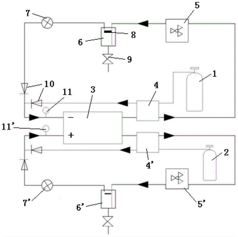
[0028] In Example 1, the oxidant gas is oxygen, that is, the fuel cell is a hydrogen-oxygen fuel cell. For the tail gas circulation system of this embodiment, the cathode side is used for circulating oxygen, and the anode side is used for circulating hydrogen; structurally, the structure and composition of the cathode side and the anode side are symmetrical, and only the structure of the cathode side will be specifically described below, namely Each device in the structure of the cathode side described below is also provided correspondingly on the anode side, and works in the same way.

[0029] In the self-heating part, the first heat exchanger 4 has two gas pipelines, which are respectively connected to the cathode tail end of the fuel cell stack 3 and the outlet end of the oxidant gas tank 1 (it can also be other oxidant supply equipment). The cathode tail gas that has reacted in the fuel cell stack 3 and the oxygen used to enter the fuel cell stack 3 for reaction will all p...

Embodiment 2

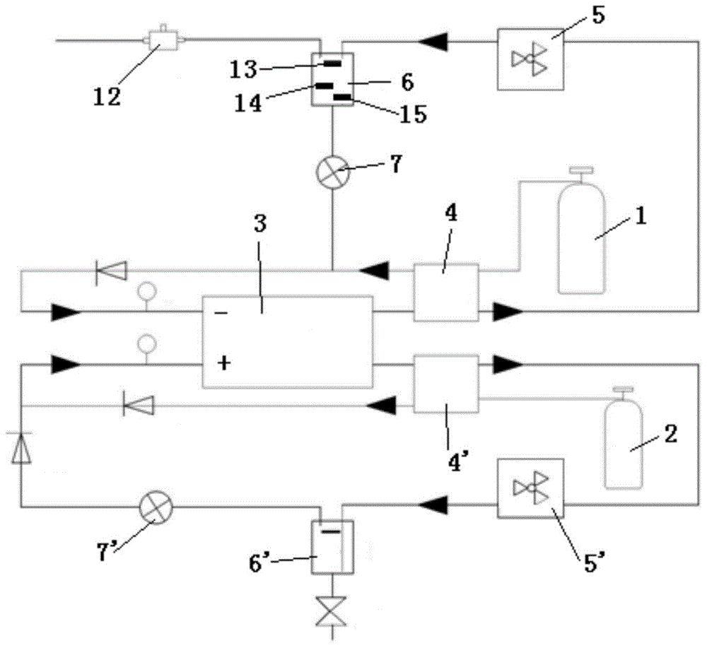
[0040] In Example 2, the oxidant gas is air, that is, the fuel cell is a hydrogen-air fuel cell.

[0041] For the exhaust gas circulation system of this embodiment, the cathode side is used to circulate air and recover the water generated by the stack to humidify the reaction air, and the anode side is used to circulate hydrogen while recovering the water generated by the stack to humidify the reaction hydrogen; the structural composition and implementation of the anode side In Example 1, the structure of the anode side is the same, but the structure of the cathode side is different, so only the structure of the cathode side will be described in detail below.

[0042] In embodiment 2, due to the reduction of the oxygen concentration in the tail gas, the cathode side structure is different compared to embodiment 1. Specifically, the first circulation pump 7 is a water pump; the first gas / water separator 6 includes an exhaust end (at the upper end), a solenoid valve at the drain...


PUM


Abstract

The invention discloses a fuel-cell tail gas circulation system. According to the system, an oxidant gas tank is connected with a cathode of a fuel cell stack and oxygen or air is introduced, a hydrogen storage tank is connected with an anode of the fuel cell stack and hydrogen is introduced, and the system comprises a first heat exchanger, a first heat sink, a first gas-water separator and a first circulating pump which are arranged at the cathode side, and a second heat exchanger, a second heat sink, a second gas-water separator and a second circulating pump which are arranged at the anode side. The fuel-cell tail gas circulation system is capable of satisfying both self-humidifying and self-heating demands of a fuel cell reaction gas, in other words, the fuel-cell tail gas circulation system realizes optimization management on temperature and humidity of inlet gases of the cathode and the anode through recovery utilization of heat and water in the tail gas, helps to reform the outer humidifying and outer heating design of a conventional hydrogen-air fuel cell, keeps a foothold on popularization and application of fuel cells, and realizes most simplified design of fuel cells.

Description

technical field [0001] The invention relates to the fields of new energy and fuel cells, in particular to a fuel cell tail gas circulation system. Background technique [0002] Proton exchange membrane fuel cell is a power generation technology that directly converts chemical energy into electrical energy through electrochemical reactions in an efficient and environmentally friendly manner. It has the advantages of fast start-up, low noise, small infrared characteristics, and non-polluting emissions. One of the main development trends. [0003] During the fuel cell power generation process, protons are transported from the anode to the cathode in the hydration mode. At the same time, in order to prevent the excessive gas flow of the cathode from causing the loss of water inside the stack, it is necessary to humidify the anode and cathode reaction gases entering the stack. [0004] Conventional hydrogen-air fuel cells often use an external humidification method, because the ...

Claims


Application Information

Patent Timeline
IPC IPC(8): H01M8/04H01M8/04007H01M8/04082H01M8/04089H01M8/04119H01M8/04291
CPCH01M8/04044H01M8/04059H01M8/04074Y02E60/50
Inventor 张洪霞辛廷慧韩福江
Owner 北京长征天民高科技有限公司
Why Eureka
Try Eureka