LED dimming system

A dimming and dimmer technology, applied in the field of LED dimming systems, can solve the problems of low efficiency of dimming systems, difficulty in networking, and easy noise generation.

Active Publication Date: 2015-03-11
HANGZHOU SILAN MICROELECTRONICS
View PDF4 Cites 5 Cited by
  • Summary
  • Abstract
  • Description
  • Claims
  • Application Information

AI Technical Summary

Problems solved by technology

At present, the thyristor dimming system still has the following problems: 1) The compatibility of the lamps is not good. The same LED bulb is easy to produce light flicker when connected to different dimmers. Some of them are caused by the difference in the minimum holding current of the thyristor. Some are caused by power grid distortion; 2) The EMI filter of the LED load device (or called the driving power supply) is prone to noise, mainly caused by the current peaks 102 and 103 at the moment the thyristor T1 is turned on, causing noise from the differential mode inductor and capacitor ; 3) The efficiency of the dimming system is low. Due to the need to be compatible with the thyristor dimmer 101, the LED load device (or drive power supply) often provides a current path to prevent the thyristor T1 from being turned off by mistake. The moment the silicon controlled silicon is turned on, it will cause excessively high dv / dt and di / dt, and it is necessary to increase damping in the input circuit, but these will lose power consumption and reduce efficiency
The disadvantages of this solution are: high standby power consumption, high cost, and difficult networking
However, no matter which of the above methods is adopted, basic hardware devices such as WIFI router 309, gateway 300, and wireless module 303 are required, resulting in complex structure of the dimming system, high cost, and large standby power consumption.

Method used


Image

  • LED dimming system
  • LED dimming system
  • LED dimming system

Examples


Embodiment Construction

[0102] The present invention will be further described below in conjunction with specific embodiments and accompanying drawings, but the protection scope of the present invention should not be limited thereby.

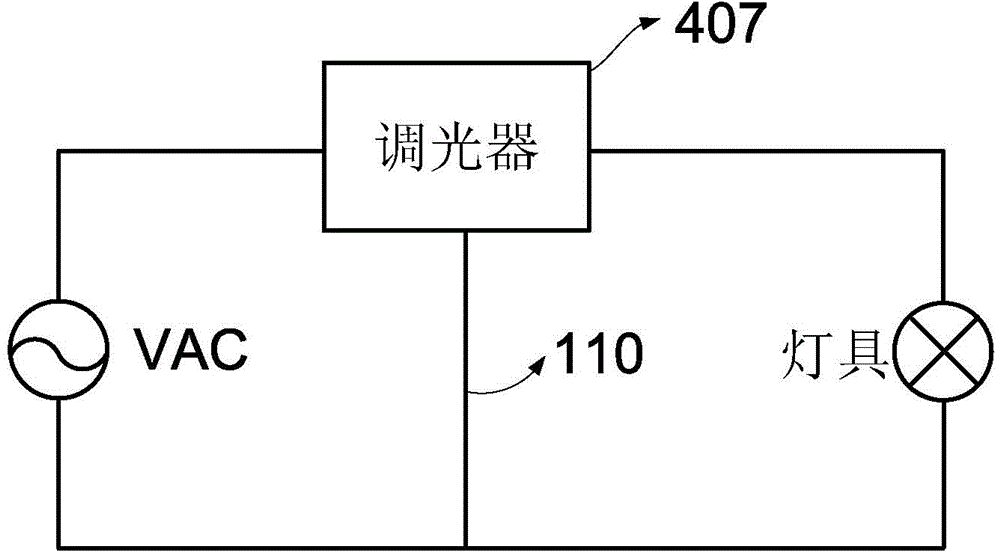
[0103] refer to Figure 6 , the LED dimming system of this embodiment includes: an AC input power supply VAC, a control unit 407 and a load device 400 .

[0104] Wherein, the load device 400 may include: a rectification circuit 401 , an EMI filter circuit 408 , a bypass circuit 402 , a zero-crossing detection circuit 403 , a data sampling circuit 404 , a controller 405 and a power conversion circuit 406 . Wherein, the controller 405 may be implemented by a microcontroller (MCU) or other appropriate components.

[0105] Preferably, the load device 400 can be integrated inside the lamp, in other words, the load device 400 can be integrated with the lamp.

[0106] Further, the AC input power supply VAC has an AC input first terminal and an AC input second terminal, and ...


PUM


Abstract

The invention provides an LED dimming system. The LED dimming system comprises an alternating current input power supply, a control unit, a loading device, a first zero cross detection circuit, a data sampling circuit, a controller and a bypass circuit, wherein the input end of the control unit is connected with an alternating current input first end; the loading device comprises a rectifier circuit which is used for rectifying an output signal of the control unit so as to generate rectifying voltage; zero cross detection is carried out on the rectifying voltage by the first zero cross detection circuit so as to generate a first zero cross detection signal; the rectifying voltage is sampled by the data sampling circuit so as to generate a data sampling signal; a bypass control signal is generated by the controller according to the first zero cross detection signal and the data sampling signal; the bypass control signal is used for controlling the switching On and Off of the bypass circuit and bypass resistance when the bypass circuit is switched On, a conducting loop is formed by the alternating current input power supply, the control unit and the bypass circuit when a bypass switch is turned on, and the conducting loop is broken off when the bypass switch is turned off. The LED dimming system can replace a traditional thyristor diming system and can further be applied to an intelligent lighting system. The cost and standby power consumption can be low.

Description

technical field [0001] The invention relates to an LED dimming system. Background technique [0002] Lighting systems usually include systems such as general household lighting, commercial lighting, road lighting and landscape lighting. At present, the lighting system of most households in China simply uses a switch to control the on and off of the light, that is, the light has only two states, either on or off. In foreign countries, especially in North American countries, household lighting involves dimming function, that is, the brightness and color of lights can be changed through control units (such as dimmers or control panels) to achieve a certain comfort level. For example, hotels, conference rooms, shopping malls and other occasions often need to control and adjust the lighting. At present, the usual adjustment method is to adjust the brightness of the light through a dimmer or a control panel, local area control, remote control, etc. Control units, such as dimmer...

Claims


Application Information

Patent Timeline
Patent Type & Authority Applications(China)
IPC IPC(8): H05B37/02
Inventor 蔡拥军叶美盼
Owner HANGZHOU SILAN MICROELECTRONICS
Why Eureka
Try Eureka