Low-energy-consumption high-pressure powder conveying device

A high-pressure conveying and low-energy-consumption technology, applied in the field of coal chemical industry, can solve problems such as poor coal-water slurry feeding effect, narrow selection range, and short service life of gasifier burners

Active Publication Date: 2015-03-25
CHINA UNIV OF PETROLEUM (EAST CHINA)
View PDF5 Cites 3 Cited by
  • Summary
  • Abstract
  • Description
  • Claims
  • Application Information

AI Technical Summary

Problems solved by technology

However, the evaporation of nearly 40% of the water in the coal-water slurry needs to absorb a large amount of heat, thereby reducing the efficiency of cold gas, increasing the consumption of oxygen and coal; There are strict requirements on melting properties, which narrow the selection range of coal, especially for low-quality coal with too low calorific value, the feeding effect of coal-water slurry is very poor; the service life of refractory bricks in gasifier is short, generally 1 ~2 years; gasifier burner life is short

Method used


Image

  • Low-energy-consumption high-pressure powder conveying device

Examples


Embodiment 1

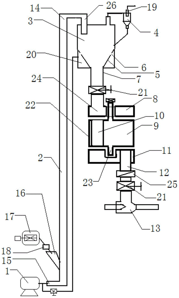
[0026]Example 1, during specific operation, after the pulverized coal is crushed into fine coal powders smaller than 150 μm by the pulverizer (17), a large amount of gas from the fan (1) enters the riser (2) through the low-pressure delivery air inlet (15), and the The fine coal powder added from the powder inlet (16) at the lower part of the riser (2) is conveyed to the top of the riser (14), and then the fine coal powder is conveyed to the upper hopper (3) through the quick separation (26). The gas passes through the gas-solid separator (4) to recover the fine coal powder and then discharges. A small amount of gas from the fan (1) is connected to the fluidization gas chamber (20) through a bypass, and then injected into the air inlet (6) on the upper side wall of the conical hopper (5) to make the fine coal in the upper hopper (3) The powder forms a fluidized state, and the fine coal powder flows into the conical hopper (5) material leg (7), and flows through the valve (21) ...

Embodiment 2

[0030] Example 2: Coal powder is replaced by coke powder, the pressure of the fan (1) is 0.03MPa, the conveying height is 50m, and the rest remain unchanged.

[0031] The powder low-energy and high-pressure conveying equipment provided by the present invention adopts low-pressure lifting, fluidized state material distribution and output, horizontal rotation and staggered discharge, and high-pressure working gas is used to pump and transport through high-pressure jet pumps, and the powder flow performance is hardly affected by gas. Influenced by pressure changes, and the requirements for the water content of pulverized coal are greatly reduced, which solves the problem of fine powder transported by dense-phase pipes from the source. Due to excessive pressure, the flow characteristics of the powder will change, resulting in difficulty in transportation and affecting the stability of the device. Difficulties in operation, avoiding the use of external high-pressure nitrogen or CO ...


PUM


Abstract

The invention provides a low-energy-consumption high-pressure powder conveying device. A low-pressure conveying air inlet is formed in the bottom of a lifting pipe. A powder inlet is formed in the lower portion of the lifting pipe. The top of the lifting pipe is connected with a feeding bin through a quick separator. The low-pressure conveying air inlet in the bottom of the lifting pipe is connected with a fan. The powder inlet in the lower portion of the lifting pipe is connected with a crusher through a feeder. A gas outlet in the top of the feeding bin is provided with a gas-solid separator. A feed leg of the gas-solid separator is returned back to the lower middle portion of the feeding bin. One to twelve conical hoppers are arranged at the bottom of the feeding bin. Air inlets are formed in the side walls of the upper portions of the conical hoppers. A fluidization gas chamber is arranged from the middles of the conical hoppers to the bottom of the feeding bin and connected with the fan through a bypass. The feed leg of each conical hopper is connected with an irregularly-shaped hole in an upper fixing valve plate of a powder conveying pump through a valve. A lower stock bin connected with an irregularly-shaped hole in a lower fixing valve plate of the powder conveying pump passes through a check valve and the valve in sequence to be connected with a high-pressure injection pump.

Description

1. Technical field [0001] The invention relates to the field of coal chemical industry, in particular, to the transportation of pulverized coal gas. 2. Background technology [0002] Coal gasification is the leading and key technology for the clean and efficient utilization of coal. Entrained entrained gasification is a new type of co-current coal gasification technology developed in recent decades. The gasification agent and coal powder or coal slurry enter the gasification chamber through the nozzle, and the pyrolysis, combustion and gasification reactions of coal are almost At the same time, the high temperature ensures efficient coal gasification, and the minerals in the coal become slag and leave the gasifier. Compared with other gasification technologies, the pressurized entrained entrained bed gasification temperature is high, the processing capacity is large, the gas active components are high, and the gasification efficiency is high. It is one of the most advanced ...

Claims


Application Information

Patent Timeline
Patent Type & Authority Applications(China)
IPC IPC(8): B65G53/16B65G53/34B65G53/40B65G53/60
Inventor 田原宇乔英云田斌
Owner CHINA UNIV OF PETROLEUM (EAST CHINA)
Why Eureka
Try Eureka