
A device and method for preparing optical fiber preform by vad method

An optical fiber preform and target rod technology, which is applied in the field of optical fiber manufacturing, can solve the problems of high probability of SIO2 particles adhering to the top of the separator, decreased stability, airflow disturbance, etc., to achieve relative position stability, stability improvement, and guaranteed stability sexual effect

Active Publication Date: 2017-07-21
YANGTZE OPTICAL FIBRE & CABLE CO LTD
View PDF1 Cites 0 Cited by
  • Summary
  • Abstract
  • Description
  • Claims
  • Application Information

AI Technical Summary

Problems solved by technology

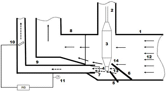
In this way, the pressures of the upper and lower parts are different, which may lead to the disturbance of the air flow in the gap between the partitions. The core layer flame has no auxiliary air supply, so its stability decreases; the uncollected SIO2 produced in the core layer deposition area Particles have a high probability of attaching to the top of the separator, and can easily fall to the surface of the core part of the powder rod during deposition, resulting in the formation of defects

Method used


Image

  • A device and method for preparing optical fiber preform by vad method
  • A device and method for preparing optical fiber preform by vad method
  • A device and method for preparing optical fiber preform by vad method

Examples


Embodiment 1

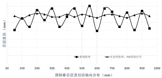
[0035] Embodiment 1: Using a common integrated exhaust duct (comparative example), the cladding and core layer gas smoke is taken away from an integral outlet. At this time, the core layer and cladding flames are at the same distance from the exhaust duct, and the fluctuation of pipeline pressure The effect on cladding and core is the same.

[0036] Install the quartz target rod on the boom and make it rotate, lower the target rod to the appropriate position in the rectangular reaction chamber and face the blowtorch. Introduce hydrogen and oxygen into the blowtorch and ignite it to generate oxyhydrogen flame; feed SiCl4 and GeCl4 gas raw materials into the core torch, which undergo hydrolysis reaction in the oxyhydrogen flame to form SiO2 and GeO2 powders and deposit them on the lower end of the target rod. The core layer of the prefabricated core rod is formed, and at the same time, the SiCl4 gas raw material is passed into the cladding blowtorch, and the generated SiO2 powde...

Embodiment 2

[0038] Embodiment 2: using the cladding-core layer separation type exhaust pipe proposed in the present invention, the distance from the inlet of the cladding exhaust pipe to the axis of the target rod is 400 mm, and the distance from the inlet of the core layer exhaust pipe to the axis of the target rod is adjusted to be 100 mm , turn on the exhaust device, set the pressure of the core layer exhaust pipe to -100Pa, and turn on the PID loop adjustment.

[0039] Install the quartz target rod on the boom and make it rotate, lower the target rod to the appropriate position in the rectangular reaction chamber and face the blowtorch. Introduce hydrogen and oxygen into the blowtorch and ignite it to generate oxyhydrogen flame; feed SiCl4 and GeCl4 gas raw materials into the core torch, which undergo hydrolysis reaction in the oxyhydrogen flame to form SiO2 and GeO2 powders and deposit them on the lower end of the target rod. The core layer of the prefabricated core rod is formed, an...

Embodiment 3

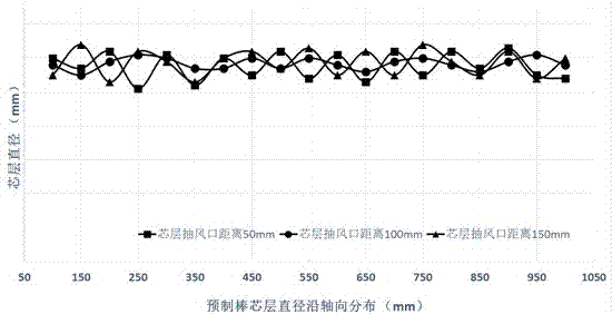
[0041] Embodiment 3: basically the same as Embodiment 2, adjust the distance from the inlet of the core layer exhaust pipe to the axis of the target rod to 50mm, set the pressure of the core layer exhaust pipe to -100Pa, and start the PID loop adjustment of the core layer discharge pipe.

[0042] After the deposited powder rods go through the vitrification process, use the preform analyzer to measure the core diameter of the preform core rod, the refractive index and other parameters to check the deposition quality of the preform ( image 3 ); when the core exhaust pressure is set at -100Pa, and the distance from the exhaust port to the center of the core deposition area is 50mm, the fluctuation range of the preform core diameter along the length direction is ±1.9%, and the standard deviation is 0.40mm. Compared with Example 2, when the air outlet of the core layer is closer to the flame of the core layer, the local draft force is too large, which may not be conducive to the st...


PUM


Abstract

The invention relates to a device and a method for preparing optical fiber preform with a VAD (vapor axial deposition) method. The device comprises a reaction chamber and a vertical rack, wherein a vertical lifting seat is arranged on the vertical rack and connected with a rotating suspender, a gas inlet end is arranged on one side of the reaction chamber, a gas outlet end is arranged at the other end of the reaction chamber, a core blow lamp and a cladding blow lamp are arranged in the reaction chamber, an opening corresponding to the core blow lamp and the cladding blow lamp is formed in the upper part of the reaction chamber and connected with an upper chamber, and the rotating suspender extends into the upper chamber. The device is characterized in that the gas outlet end is connected with a cladding gas outlet pipeline and a core gas outlet pipeline respectively, the cladding gas outlet pipeline is located above the gas outlet end, and the core gas outlet pipeline is located below the gas outlet end. The stability of core flame and a core deposition zone is guaranteed through control of a pressure feedback system in a deposition process. The stability of the flame in the core deposition zone can be effectively guaranteed, deposition of the preform core is stable and controllable, so that basic parameters such as the diameter of the preform core are uniformly distributed along the preform length, finally, the stability of the core diameter is guaranteed, and the manufacturing quality of the preform is improved.

Description

technical field [0001] The invention relates to a device and a method for preparing an optical fiber preform by a VAD method, and belongs to the technical field of optical fiber manufacturing. Background technique [0002] Currently known manufacturing processes for optical fiber preforms typically include in-tube vapor deposition processes, such as MCVD (modified chemical vapor deposition) improved chemical vapor deposition process and PCVD (plasmachemical vapor deposition) plasma excited chemical vapor deposition method; Vapor deposition process, such as OVD (outside vapor deposition) external vapor deposition process and VAD (vapor axial deposition) external axial deposition process. [0003] In-tube vapor deposition process, such as PCVD process, uses SiCl4, GeCl4, O2 and other chemical raw materials, which are passed into the high-purity quartz liner, which is beneficial to the microwave source to provide energy, excite plasma, and chemical reactions occur to form SiO2,...

Claims


Application Information

Patent Timeline
Patent Type & Authority Patents(China)
IPC IPC(8): C03B37/018
CPCC03B37/01413C03B37/0144C03B37/01446C03B2201/20C03B2201/31C03B2203/22C03B2207/20C03B2207/26C03B2207/28C03B2207/64C03B2207/66C03B37/01406Y02P40/57
Inventor 黄利伟张宏胜王瑞春顾立新孙建华朱方龙渠驰张文俊杨轶
Owner YANGTZE OPTICAL FIBRE & CABLE CO LTD
Learn More