
Lake buffer zone building method for non-point source pollution control

A non-point source pollution and buffer zone technology, applied in chemical instruments and methods, construction, biological water/sewage treatment, etc., to achieve the effect of reducing non-point source pollution load, simple operation, and realizing resource utilization

Active Publication Date: 2015-03-25
CHINESE RES ACAD OF ENVIRONMENTAL SCI
View PDF5 Cites 16 Cited by
  • Summary
  • Abstract
  • Description
  • Claims
  • Application Information

AI Technical Summary

Problems solved by technology

[0006] The technical problem to be solved by the present invention is to control non-point source pollution, especially nitrogen and phosphorus in non-point source pollution, and provide a lake buffer zone construction method with the characteristics of good purification effect, easy operation, and low cost

Method used


Image

  • Lake buffer zone building method for non-point source pollution control
  • Lake buffer zone building method for non-point source pollution control

Examples


Embodiment 1

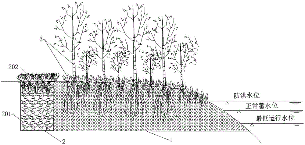
[0025] Such as figure 1 As shown, the lake buffer zone construction method for non-point source pollution control of the present invention comprises the following steps: select the area between farmland, villages and lakes (the range between the flood control level and the minimum operating water level is 1.7m) as the basis to establish the buffer zone , the buffer zone includes a vegetation zone 1 planted with native plants 3, the end away from the lake is the front end, and a reinforced matrix zone 2 is constructed at the front end of the vegetation zone 1, which is composed of an adsorption matrix 201 and herbs planted thereon Plant 202 constitutes. The adsorption matrix is ​​a mixture of red soil and waste sludge from water supply plants, in which Fe in red soil 2 o 3 The mass ratio accounts for 16.2%; the waste sludge of the water supply plant is the sludge produced by the water supply plant with aluminum salt as the flocculant, Al 2 o 3 The mass ratio accounts for 8....

Embodiment 2

[0030] The difference from Example 1 is that the adsorption matrix 201 is a mixture of red soil and waste sludge from a water supply plant, and the mixing ratio of the two is 2:1.

Embodiment 3

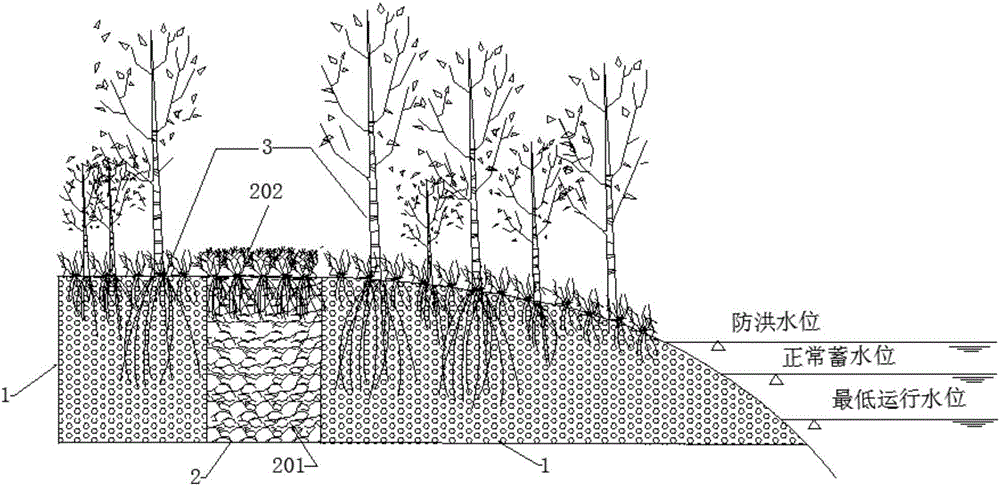
[0032] Such as figure 2 As shown, the difference from Embodiment 1 is that a reinforced matrix belt 2 is constructed in the middle of the vegetation belt 1 . The reinforced matrix belt 2 is composed of an adsorption matrix 201 and herbaceous plants 202 planted on it. The adsorption matrix 201 is a mixture of red soil and waste sludge from a water supply plant. Fe in the red soil 2 o 3 The mass percentage is 20.7%; the waste sludge of water supply plant is the sludge produced by water supply plant with aluminum salt as flocculant, Al 2 o 3 The mass ratio of the two is 6.3%, and the mixing ratio of the two is 3:1.

[0033] The base of the vegetation zone 1 is the original silty soil in the area between farmland, villages and lakes (the difference between the flood control level and the lowest water level is 1.7m), and the native plants are mainly trees such as red willow and metasequoia and herbaceous plants such as Bermuda. Vegetation zone 1 has a width of 100m, its end st...


PUM

PropertyMeasurementUnit
widthaaaaaaaaaa
widthaaaaaaaaaa
depthaaaaaaaaaa

Abstract

The invention discloses a lake buffer zone building method for non-point source pollution control. The method includes the following steps that a region among a farmland, a village and a lake is selected to serve as the foundation to build a buffer zone. The buffer zone comprises a vegetational zone (1) planted with indigenous plants (3). The end, away from the lake, of the vegetational zone (1) is the front end, and a reinforcement substrate zone (2) is built at the front end or the middle of the vegetational zone (1). The lake buffer zone building method for non-point source pollution control which is good in purifying effect, easy to operate and low in cost is provided for control over non-point source pollution and particularly control over nitrogen and phosphorus in the non-point source pollution.

Description

technical field [0001] The invention relates to the field of water pollution control and ecological restoration, in particular to a lake buffer zone construction method for non-point source pollution control. Background technique [0002] In recent years, with the rapid development of the lake basin economy, dense population and unreasonable development have made the lakeside area become an area with dense pollution sources in the lake basin, and the lakeside ecological environment has been damaged to varying degrees. Its function as a "natural barrier" of the lake has gradually The problem of eutrophication of lakes has become increasingly prominent. Due to the sensitivity and importance of the lakeside area to lake protection, the research on the lakeside area has gradually become a hot issue in the field of lake protection. [0003] The lakeside area is the junction area between land and water, and also the junction area between surface water and groundwater, which has t...

Claims


Application Information

Patent Timeline
Patent Type & Authority Applications(China)
IPC IPC(8): E02B3/00C02F3/32
CPCC02F3/32E02B3/00Y02W10/10
Inventor 储昭升高思佳叶碧碧庞燕胡小贞
Owner CHINESE RES ACAD OF ENVIRONMENTAL SCI
Learn More