
Movable type deep well burning oil layer ignition tubular column and ignition method thereof

A mobile technology for burning oil layers, which is applied in earthwork drilling, wellbore/well components, and production fluids, etc. It can solve the problems of high risk, difficulty, and increased cost of single well operation, and improve the success rate of ignition , reduce investment costs, and ensure construction safety

Active Publication Date: 2015-03-25
PETROCHINA CO LTD
View PDF10 Cites 1 Cited by
  • Summary
  • Abstract
  • Description
  • Claims
  • Application Information

AI Technical Summary

Problems solved by technology

The bundled igniter is to use the oil pipe string to lower the igniter into the target layer, and tie its power cable to the oil pipe to connect with the ground control cabinet. The gas injection pipe will not be released during the entire production cycle, resulting in The portable electric igniter and power cable were burnt out and could not be reused, resulting in an increase in the cost of a single well
In addition, during the ignition process, the monitoring cable must be lowered from the casing, and the operation risk is relatively high, and the monitoring of the whole process and the whole section cannot be realized.
[0005] Chinese patent 201110326453.X discloses a removable electric igniter, which can be used repeatedly, but because the igniter and the power cable are not equal in diameter, it is difficult to operate the wellhead during the entire gas injection cycle. Larger and does not have a complete temperature monitoring system
Chinese patent 201320112187.5 discloses a retractable electric ignition and monitoring system for burning oil layer, in which the igniter used is a mobile electric igniter that can be reused, but the monitoring of the air temperature at the outlet of the igniter is carried out with the oil pipe string The independent single thermocouple monitoring system is implemented, and the on-site construction process of the temperature monitoring system along with the pipe string is complicated and the construction cost is high, and because the pipe string is fixed, the well temperature profile test in the longitudinal direction of the oil layer cannot be realized during the ignition process

Method used


Image

  • Movable type deep well burning oil layer ignition tubular column and ignition method thereof
  • Movable type deep well burning oil layer ignition tubular column and ignition method thereof

Examples


Embodiment Construction

[0027] The following will clearly and completely describe the technical solutions in the embodiments of the present invention with reference to the accompanying drawings in the embodiments of the present invention. Obviously, the described embodiments are only some, not all, embodiments of the present invention. Based on the embodiments of the present invention, all other embodiments obtained by persons of ordinary skill in the art without making creative efforts belong to the protection scope of the present invention.

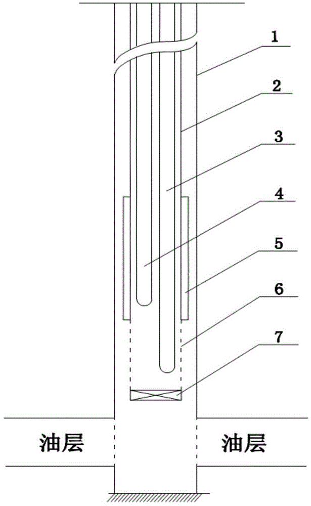
[0028] Such as figure 1 As shown, the present invention provides a mobile deep well fire oil layer ignition string, the mobile deep well fire oil layer ignition string includes: casing 1, oil pipe 2, high temperature insulation pipe 5, high temperature screen 6, plug 7, Coiled tube electric igniter 4 and coiled tube fiber optic ultra-high temperature temperature measuring cable 3 .

[0029] Casing 1 goes deep below the oil layer. The oil pipe 2 is arranged i...


PUM

PropertyMeasurementUnit
Diameteraaaaaaaaaa
Diameteraaaaaaaaaa
Diameteraaaaaaaaaa

Abstract

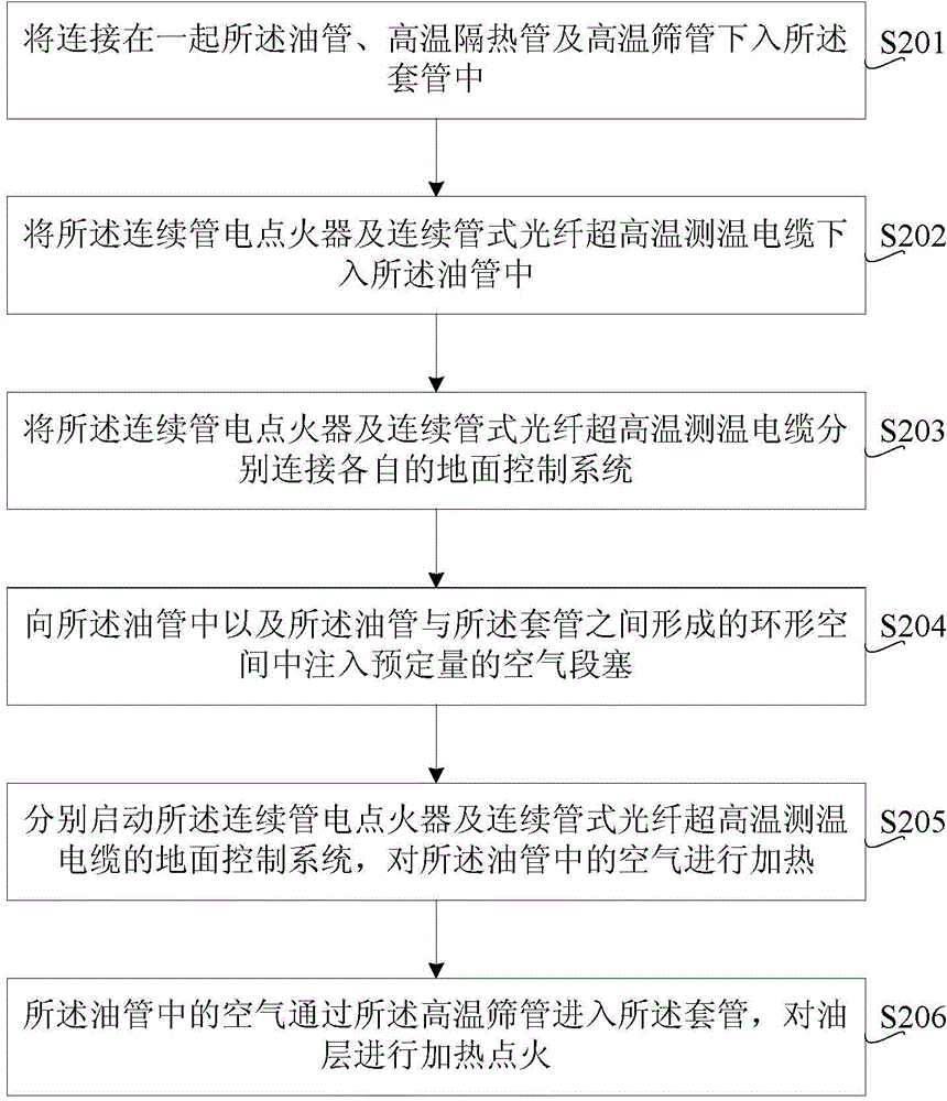
The invention discloses a movable type deep well burning oil layer ignition tubular column and an ignition method of the tubular column. The ignition method comprises the steps that an oil tube, a high-temperature heat-insulating tube and a high-temperature screen tube which are connected together are sent to a casing tube; a continuous tube electric igniter and a continuous tube type optical fiber ultra-high-temperature measuring cable are sent to the oil tube; the continuous tube electric igniter and the continuous tube type optical fiber ultra-high-temperature measuring cable are connected to respective ground control systems respectively; air section plugs with the number on schedule are injected into the oil tube and annular space formed between the oil tube and the casing tube; the ground control system of the continuous tube electric igniter and the ground control system of the continuous tube type optical fiber ultra-high-temperature measuring cable are started respectively, and air in the oil tube is heated; the air in the oil tube enters the casing tube through a high-temperature screen tube, and heating ignition is carried out on the oil layer. The movable type deep well burning oil layer ignition tubular column can protect an ignition device and an underground tubular column, and the ignition success rate is improved.

Description

technical field [0001] The present invention relates to oil recovery technology of burning oil layer, in particular to a mobile deep well burning oil layer ignition pipe string and an ignition method thereof. Background technique [0002] Burning the oil layer is to inject air or oxygen into the oil reservoir through the burning injection well, make it react with some heavy components in the oil layer in the oil layer, and use the heat generated by the reaction and the tail gas to drive the crude oil out of the ground, and this process The key to achieving sustainability is reservoir ignition. At present, the ignition methods used mainly include spontaneous ignition, chemical ignition and electric ignition, among which electric ignition is the most widely used ignition method. This method has the advantages of mature supporting technology, easy ignition control and high ignition success rate. features. [0003] The existing electric ignition technology is limited by the ig...

Claims


Application Information

Patent Timeline
IPC IPC(8): E21B43/243
CPCE21B43/243
Inventor 阚长宾高立江汪小平于晓聪汪淼杜新军王占胜
Owner PETROCHINA CO LTD
Learn More