
A finned plate heat exchange device for condensing flue gas waste heat recovery

A flue gas waste heat and heat exchange device technology, which is applied in the field of finned plate heat exchange devices, can solve the problems of flue gas condensation waste heat recovery devices, such as easy corrosion, difficult space layout, and high investment cost, and achieve compact structure and enhanced heat transfer , The effect of low equipment cost

Active Publication Date: 2016-04-13
CHINA PETROLEUM & CHEM CORP +1
View PDF6 Cites 0 Cited by
  • Summary
  • Abstract
  • Description
  • Claims
  • Application Information

AI Technical Summary

Problems solved by technology

[0006] The technical problem to be solved by the present invention is that the existing flue gas condensation waste heat recovery device is easy to corrode, has low heat exchange efficiency, is not compact in structure, difficult in space arrangement, and high in investment cost

Method used


Image

  • A finned plate heat exchange device for condensing flue gas waste heat recovery
  • A finned plate heat exchange device for condensing flue gas waste heat recovery
  • A finned plate heat exchange device for condensing flue gas waste heat recovery

Examples


Embodiment Construction

[0021] The present invention will be further described below in conjunction with the accompanying drawings.

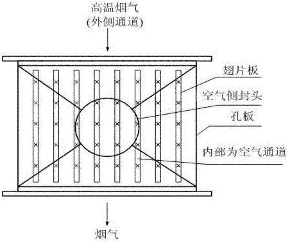
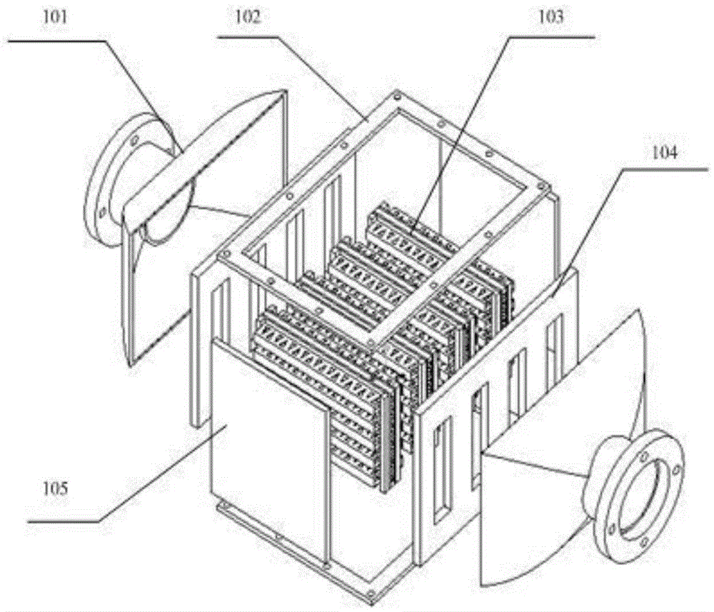
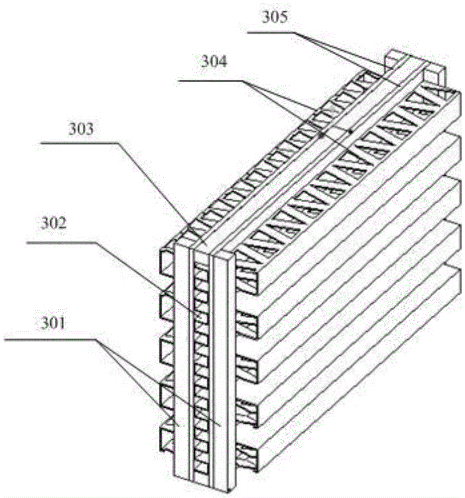
[0022] like figure 1 As shown, the present invention includes two orifice plates and an arc-shaped end plate combined head welded with the two orifice plates, two sealing plates and upper and lower flanges, as well as a clamp placed between the two orifice plates, There are more than one finned plates of the same size arranged in parallel; there is a flue gas channel between adjacent finned plates, and the two ends of the channel are connected to the flue gas side; the inside of the finned plates is an air channel, and the two ends of the channel are connected Air side: the air in the air channel and the flue gas in the flue gas channel flow in a staggered direction, the flue gas side of the fin plate adopts horizontal rows of triangular porous fins, and the air side adopts variable-pitch zigzag fins. The high-temperature flue gas enters from one end of the flue gas s...


PUM

PropertyMeasurementUnit
heightaaaaaaaaaa
porosityaaaaaaaaaa

Abstract

The invention discloses a fin plate heat exchanger for condensing waste heat recovery. The heat exchanger comprises two pore plates, an arc end plate combination seal welded to the pore plates, two seal plates, upper and lower square flanges, and more than one fin plates; the fin plates are arranged between the pore plates parallelly and are same in size; smoke channels are formed between the adjacent fin plates, and two ends of the channels are communicated with the smoke sides; air channels are formed in the fin plates, and two ends of the channels are communicated with the air sides; the air in the air channels and the smoke in the smoke channels flow in a staggered manner; the smoke sides of the fin plates are provided with transverse triangular porous fins, and the air sides are provided with variable spacing serrated fins. The heat exchanger is compact and simple in structure and convenient to install; the resistance of the smoke sides is small, scaling is prevented, dew point corrosion can be prevented effectively, and the service life is long; the vaporization latent heat of the vapor of the smoke can be recovered effectively, the waste heat utilization rate is high, and the equipment cost is low.

Description

technical field [0001] The invention relates to a chemical engineering device, in particular to a finned plate heat exchange device for recovery of condensed flue gas waste heat. Background technique [0002] The world's first condensing waste heat recovery gas boiler was born in the Netherlands in 1979 and began engineering application in 1980. Due to its obvious energy-saving and environmental protection benefits, it has developed rapidly in North America and Europe since the 1980s, and has been widely used in Britain, Germany and France since the early 1990s. However, domestic research on gas-fired heating furnaces, especially gas-fired heating furnaces for recovery of condensation waste heat, is lagging behind. [0003] There are a large number of fuel-gas industrial heating furnaces in the petrochemical industry. The exhaust gas of industrial heating furnaces has high moisture content, and the exhaust gas temperature of conventional waste heat recovery is above the dew...

Claims


Application Information

Patent Timeline
Patent Type & Authority Patents(China)
IPC IPC(8): F28D9/02F28F3/04F28F19/06
CPCY02P20/10
Inventor 史永红凌祥温鸣科彭浩
Owner CHINA PETROLEUM & CHEM CORP
Learn More