
In-situ test device of high-pressure and low-temperature heat conductivity coefficients and heat transfer coefficients

A high-pressure low-temperature, heat transfer coefficient technology, applied in the field of heat transfer testing, can solve the problem of not achieving simultaneous measurement of thermal conductivity and heat transfer coefficient, changes in the physical properties and state of multiphase substances, poor ease of use and operation convenience, etc. problems, to meet the requirements of the parameters of the equipment, the structure design is compact and reasonable, and it is easy to replace

Active Publication Date: 2015-03-25
DALIAN UNIV OF TECH
View PDF7 Cites 6 Cited by
  • Summary
  • Abstract
  • Description
  • Claims
  • Application Information

AI Technical Summary

Problems solved by technology

The traditional hot wire method and flat surface heat source method are widely used to measure the thermal conductivity of samples under normal pressure conditions, but less used under low temperature and high pressure conditions, especially in the presence of multiphase conditions. Operational convenience is poor
In addition, because the traditional hot wire method and the flat surface heat source method usually generate a large amount of heat, under the coexistence of multiphase substances, it is easy to cause changes in the physical properties and states of the multiphase substances, resulting in large measurement errors. In the application There are certain limitations in the process, and the simultaneous measurement of thermal conductivity and heat transfer coefficient has not been realized in the traditional hot wire method and flat surface heat source method.
At present, there is no report on the in situ measurement of thermal conductivity and heat transfer coefficient in multiphase state under high pressure and low temperature conditions.

Method used


Image

  • In-situ test device of high-pressure and low-temperature heat conductivity coefficients and heat transfer coefficients
  • In-situ test device of high-pressure and low-temperature heat conductivity coefficients and heat transfer coefficients
  • In-situ test device of high-pressure and low-temperature heat conductivity coefficients and heat transfer coefficients

Examples


Embodiment Construction

[0018] The specific implementation manners of the present invention will be further described below in conjunction with the accompanying drawings and technical solutions.

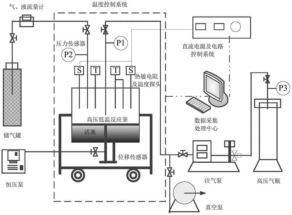
[0019] Figure 1-4 A high-pressure low-temperature thermal conductivity and heat transfer coefficient in-situ test device is demonstrated. The device mainly consists of two parts. The first part is the thermistor measurement probe, such as figure 1 As shown, first clean the lead wire of the thermistor, insulate it with insulating varnish, and repeat it three times. After testing that the insulation is good, pass the lead wire of the thermistor through the perforated thin steel pipe, and fill the thin steel pipe with epoxy resin, and at the same time Wrap the thermistor wire to stabilize the thermistor, then pass the thermistor wire through the high-pressure sealing device, and at the same time insert the perforated thin steel pipe into the front section of the high-pressure sealing device and fix it with ...


PUM


Abstract

The invention discloses an in-situ test device of high-pressure and low-temperature heat conductivity coefficients and heat transfer coefficients. The in-situ test device comprises a high-pressure and low-temperature reaction kettle, a thermistor measurement probe, a power supply input control system and a data acquisition system, wherein a thermistor and a control circuit board are arranged in the measurement probe; the measurement probe is sealed by virtue of a high-pressure seal ring; a side resistor and a circuit protection device are arranged on the circuit board; a connecting lead with an insulating paint coating passes through a fine stainless steel tube, then passes through a high-pressure seal device, and is pressed and sealed by pressure-proof plastic; the fine stainless steel tube is spliced and fixed to the seal device by using epoxy resin; holes are uniformly formed in the fine stainless steel tube; two chambers of the high-pressure and low-temperature reaction kettles are connected with each other by virtue of a piston; and a measured sample is directly put into the upper chamber of the high-pressure and low-temperature reaction kettle. The piston is pushed by injecting liquid into the lower end of the high-pressure and low-temperature reaction kettle through a constant pressure pump, so that the measured sample in the chamber is pressed in a standardizing manner; the in-situ test device can meet the requirements of in-situ synthesis of different mediums under high pressure and at low temperature and can be used for carrying out in-situ measurement on the heat conductivity coefficients and the heat transfer coefficients of multi-phase substances in different spaces and different time.

Description

technical field [0001] The invention relates to an in-situ testing device for high-pressure and low-temperature thermal conductivity and heat transfer coefficient, belonging to the technical field of heat transfer testing. Background technique [0002] It is a relative measurement method to measure the thermal conductivity and heat transfer coefficient of different media based on the thermistor point heat source method. Supply the power specified by the thermistor through the DC power supply to make the thermistor self-heat, and the thermistor is in direct contact with the measurement object for in-situ measurement, and calculate the thermal conductivity of the medium to be measured according to the temperature attenuation data of the thermistor itself and using the calculation model and heat transfer coefficient. This technical method can be applied to measure the internal thermal conductivity and heat transfer coefficient of different porous media under different conditio...

Claims


Application Information

Patent Timeline
Patent Type & Authority Applications(China)
IPC IPC(8): G01N25/20
Inventor 赵佳飞程传晓宋永臣王斌杨磊朱自浩
Owner DALIAN UNIV OF TECH
Learn More