Laser distance measurement target indicator and distance measurement method thereof and working state switching method

A technology of target indicator and laser ranging, which is applied in the direction of instruments, measuring devices, radio wave measuring systems, etc., can solve the problem of the comprehensive application of signal video accumulation and binary accumulation, which affects the effective judgment of range measurement target signals, There are no problems such as laser target indication function, so as to achieve effective identification, reduce the volume of equipment, and reduce the weight of equipment

Active Publication Date: 2015-03-25
扬州郁金光子技术有限公司
View PDF3 Cites 8 Cited by
  • Summary
  • Abstract
  • Description
  • Claims
  • Application Information

AI Technical Summary

Problems solved by technology

[0003] The laser rangefinder in the American airborne "door police" photoelectric warning system, and a domestic vehicle-mounted air-to-air laser rangefinder all use the three-pulse laser rangefinder method, although the range is greatly improved compared with the single-pulse laser rangefinder , but these laser rangefinders still have the following deficiencies: (1) The hardware uses a xenon lamp-pumped solid-state laser, which consumes more power and volume than a single-pulse laser rangefinder; (2) only has a single laser rangefinder function, not It has the function of laser target indication; (3) Since the discharge characteristics of the xenon lamp will be affected by the ambient temperature and long-term use, the three pulse laser energies output by the laser cannot always be consistent, which will affect the...

Method used


Image

  • Laser distance measurement target indicator and distance measurement method thereof and working state switching method
  • Laser distance measurement target indicator and distance measurement method thereof and working state switching method
  • Laser distance measurement target indicator and distance measurement method thereof and working state switching method

Examples


Embodiment Construction

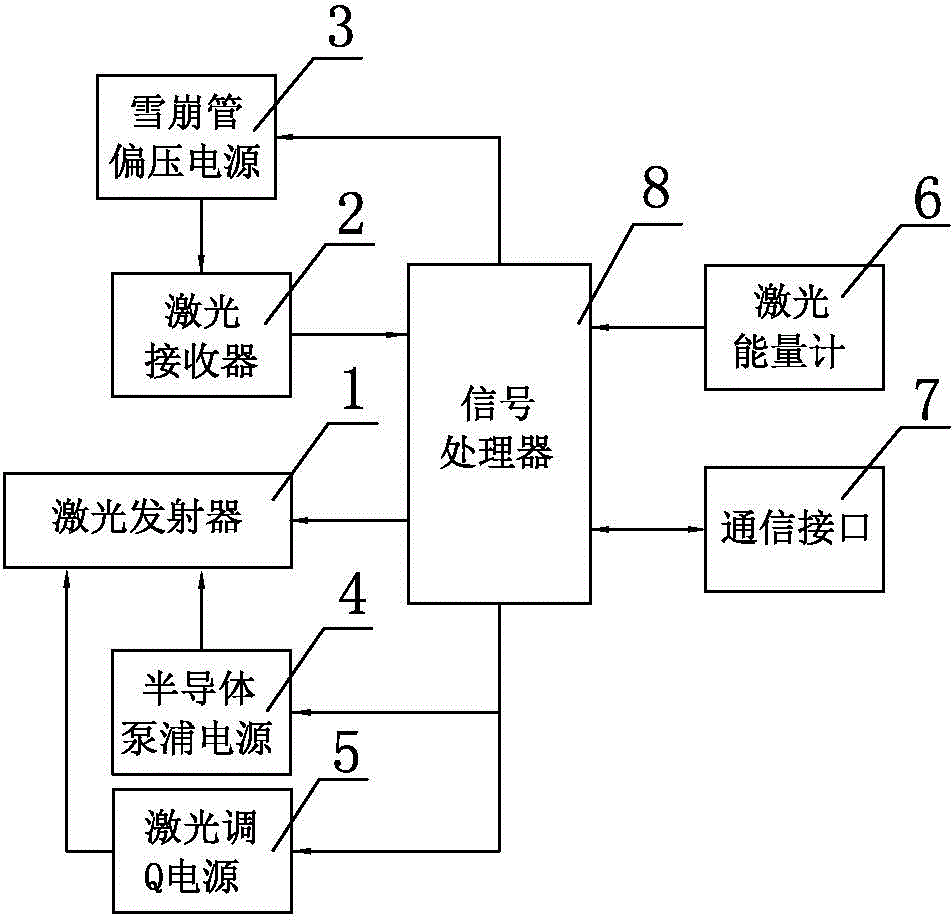
[0065] Such as figure 1 A laser ranging target designator shown, including:

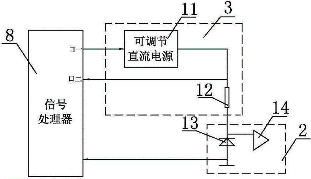
[0066] Laser transmitter 1 is used to emit multi-pulse laser beams and coded laser beams; the laser receiver 2 includes an avalanche tube 13 and an amplifier 14; the avalanche tube bias power supply 3 includes a signal processor port one, a signal processing Port 2, adjustable DC power supply 11, sampling resistor 12, signal processor port 1 is connected with adjustable DC power supply 11, used to adjust the output voltage of adjustable DC power supply 11; signal processor port 2 is connected with adjustable DC power supply at the same time The output of 11 is connected with the sampling resistor 12 for reading the operating current value of the avalanche tube 13; the sampling resistor 12 is connected with the avalanche tube 13;

[0067] The laser receiver 2 is used to receive the laser echo signal reflected by the target, convert the laser echo signal into an electrical signal, amplify the electri...


PUM


Abstract

The invention discloses a remote laser distance measurement target indicator in the field of laser distance measurement. The remote laser distance measurement target indicator comprises a laser transmitter, a laser receiver, an avalanche transistor grid bias power supply, a semiconductor pumping source power supply, a laser Q-switching power supply, a laser energy meter, a communication interface and a signal processor. Based on the time uncorrelated principle of signals and noise, weak target signals in the noise can be distinguished, and the distance measurement capacity for remote distance measurement is achieved; by the adoption of a semiconductor pumping source laser, high-frequency and multiple-pulse laser transmitting is achieved under the condition of not increasing hardware spending; switching of the two functions of laser distance measurement and target indication is achieved through software control; due to improvements on a distance measurement method and a control method, the weight of equipment is reduced directly and indirectly, the size of the equipment is reduced, the predicated weight and size are only one quarter that of a traditional xenon lamp pumping source laser distance measurement machine, and the remote laser distance measurement target indicator can be used for remote distance measurement.

Description

technical field [0001] The invention relates to a laser ranging device, in particular to a laser ranging target indicator with target indicating function. Background technique [0002] Most of the traditional solid-state pulse laser rangefinders use single-pulse laser rangefinder, which has limited rangefinder capability and needs to improve the rangefinder capability, which can only increase the output laser energy, resulting in a series of problems such as bulky size, increased power consumption, and increased weight. The problem has increased the difficulty of optoelectronic system airborne. [0003] The laser rangefinder in the American airborne "door police" photoelectric warning system, and a domestic vehicle-mounted air-to-air laser rangefinder all use the three-pulse laser rangefinder method, although the range is greatly improved compared with the single-pulse laser rangefinder , but these laser rangefinders still have the following deficiencies: (1) The hardware u...

Claims


Application Information

Patent Timeline
IPC IPC(8): G01S7/51G01S7/48G01S17/08
CPCG01S17/06G01S17/10
Inventor 郁麒麟孙同春范华夏星姚亚斌隋庆峰
Owner 扬州郁金光子技术有限公司
Why Eureka
Try Eureka