Supercharge Your Innovation With Domain-Expert AI Agents!

Power amplifying type logic control circuit based on source electrode follower

A technology of logic control circuit and source follower, which is applied in the field of logic control circuit, can solve the problems of slow running speed, complex structure of logic control circuit, high energy consumption, etc., and achieve the effects of stable performance, fast operation speed and low energy consumption

Inactive Publication Date: 2015-03-25
CHENGDU ZHILIDA TECH
View PDF0 Cites 0 Cited by
  • Summary
  • Abstract
  • Description
  • Claims
  • Application Information

AI Technical Summary

Problems solved by technology

[0004] The purpose of the present invention is to overcome the defects of complex structure, high energy consumption and slow running speed of the logic control circuit used in the current LED lamp protection system, and to provide a brand-new power amplification logic control circuit based on source follower

Method used


Image

  • Power amplifying type logic control circuit based on source electrode follower

Examples


Embodiment

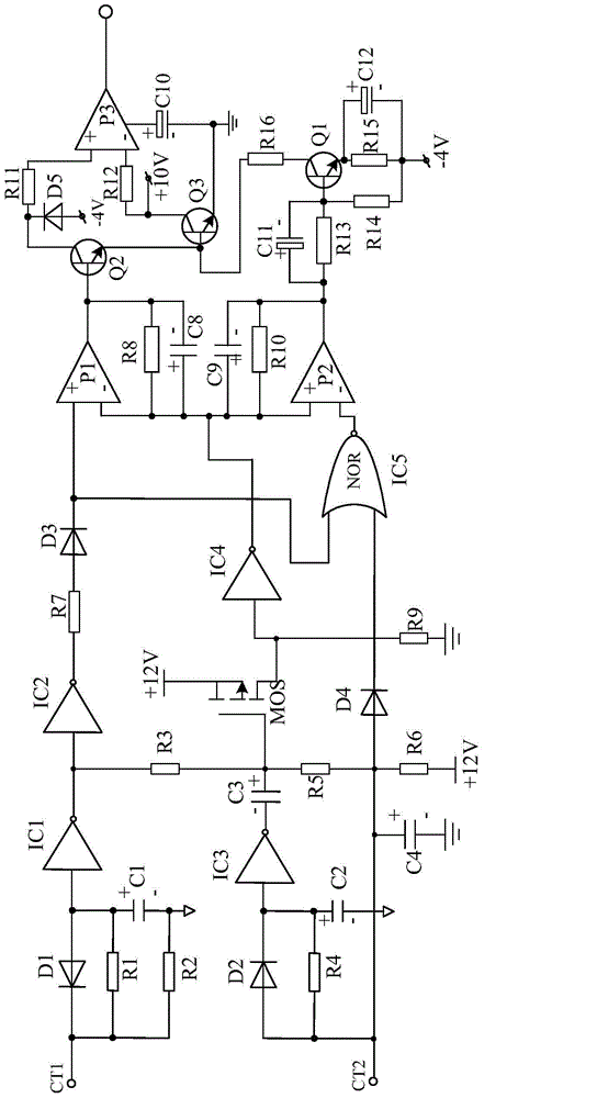
[0018] Such as figure 1 As shown, the present invention mainly consists of field effect transistor MOS, NOT gate IC1, NOT gate IC3, NOT gate IC4, primary filter circuit, secondary filter circuit, XOR gate circuit, resistor R3, resistor R5, resistor R7, resistor R9 , Capacitor C3, diode D3 and switching power amplifier circuit. When connected, the input terminal of the NOT gate IC2 is connected with the output terminal of the NOT gate IC1, that is, the NOT gate IC1 and the NOT gate IC2 are connected in series. At the same time, the primary filter circuit is connected to the input terminal of the NOT gate IC1, and the secondary filter circuit is connected to the input terminal of the NOT gate IC3.

[0019] Wherein, the switching power amplifying circuit is mainly composed of a power amplifier P1, a power amplifier P2, a power amplifier P3, a triode Q1, a triode Q2, and a triode Q3, which are connected in series between the output terminal of the power amplifier P1 and the negat...


PUM


Abstract

The invention discloses a power amplifying type logic control circuit based on a source electrode follower. The power amplifying type logic control circuit is characterized in that the circuit is mainly composed of a field-effect transistor MOS, a negater IC1, a negater IC3, a negater IC4, a negater IC2, a filter delay circuit, a first-level filter circuit, a second-level filter circuit, an exclusive-or gate circuit, a resistor R3 and the like, wherein the input end of the negater IC2 is connected with the output end of the negater IC1, the filter delay circuit is connected with the output end of the negater IC2, the first-level filter circuit is connected with the input end of the negater IC1, the second-level filter circuit is connected with the input end of the negater IC3, the exclusive-or gate circuit is connected with the output end of the negater IC4, one end of the resistor R3 is connected with the grid of the field-effect transistor MOS, and the other end of the resistor R3 is connected with the output end of the negater IC1. The power amplifying type logic control circuit is simple in overall structure and very convenient to manufacture and use, and meanwhile, the logic control function of the circuit is achieved totally depending on a logic electronic element, so that the circuit is very low in energy consumption and high in calculation speed.

Description

technical field [0001] The invention relates to a logic control circuit, in particular to a power amplification logic control circuit based on a source follower. Background technique [0002] At present, due to the characteristics of low energy consumption, long service life, safety and environmental protection, LED lamps have become one of the mainstream products for people's living lighting. Since LED lamps are different from traditional incandescent lamps, they need to be driven by a dedicated drive circuit, so there are various protection systems on the market to prevent the drive system from being interfered by internal or external adverse factors. [0003] The logic control circuit is an important control part of the LED lamp protection system, and its running speed and performance stability directly determine the use range and performance of the LED lamp protection system. However, at present, the structures of these logic control circuits are relatively complicated,...

Claims


Application Information

Patent Timeline
IPC IPC(8): H05B37/02
CPCY02B20/00
Inventor 肖尤花杜琴
Owner CHENGDU ZHILIDA TECH
Features
  • R&D
  • Intellectual Property
  • Life Sciences
  • Materials
  • Tech Scout
  • Unparalleled Data Quality
  • Higher Quality Content
  • 60% Fewer Hallucinations
Learn More