

Flame tube head assembly brazing method
A flame tube head, brazing method technology, applied in the combustion method, welding medium, welding equipment and other directions, can solve the problems of discontinuous brazing seam, blockage of cold air holes, and insufficient brazing rate of sleeve and eddy current device. , to achieve the effect of strong operability and avoiding oxidation
- Summary
- Abstract
- Description
- Claims
- Application Information
AI Technical Summary
Problems solved by technology
Method used
Image

Examples
Embodiment 1
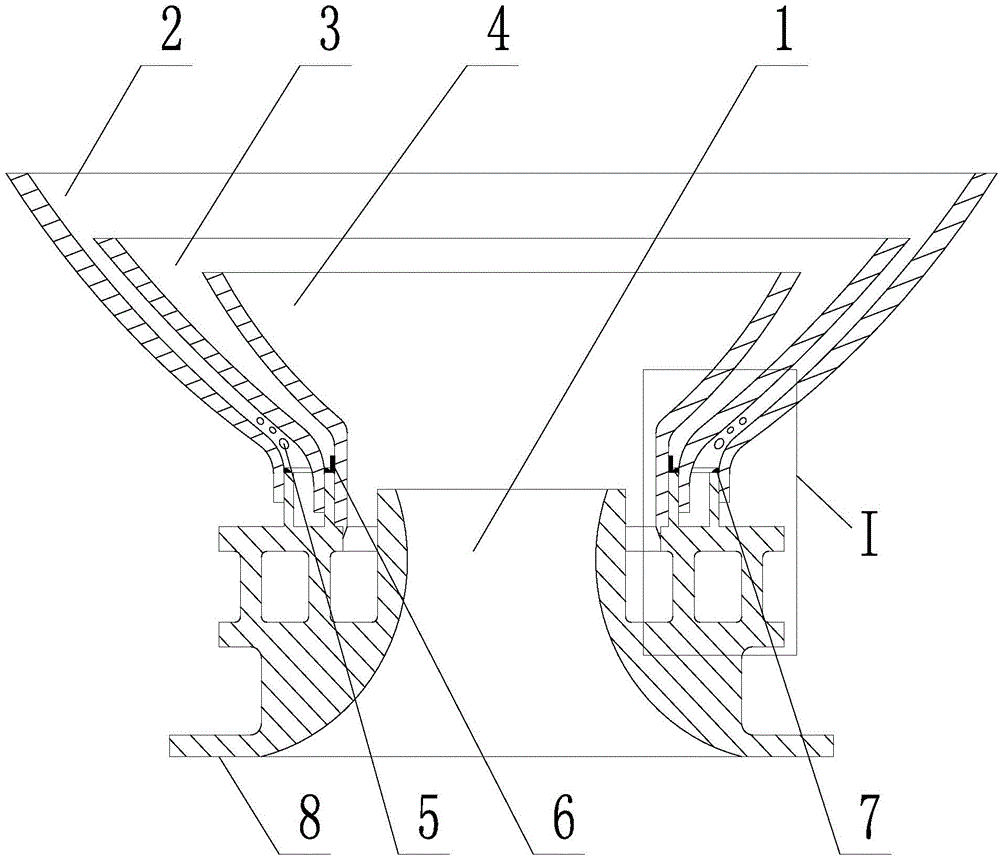
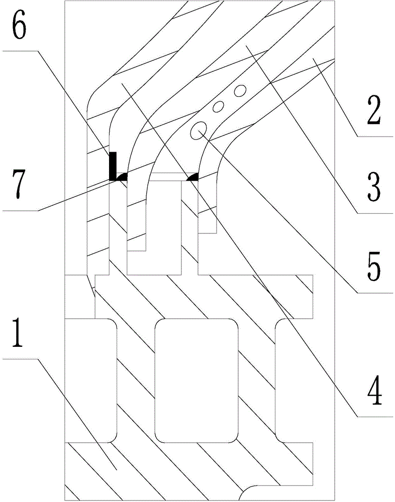
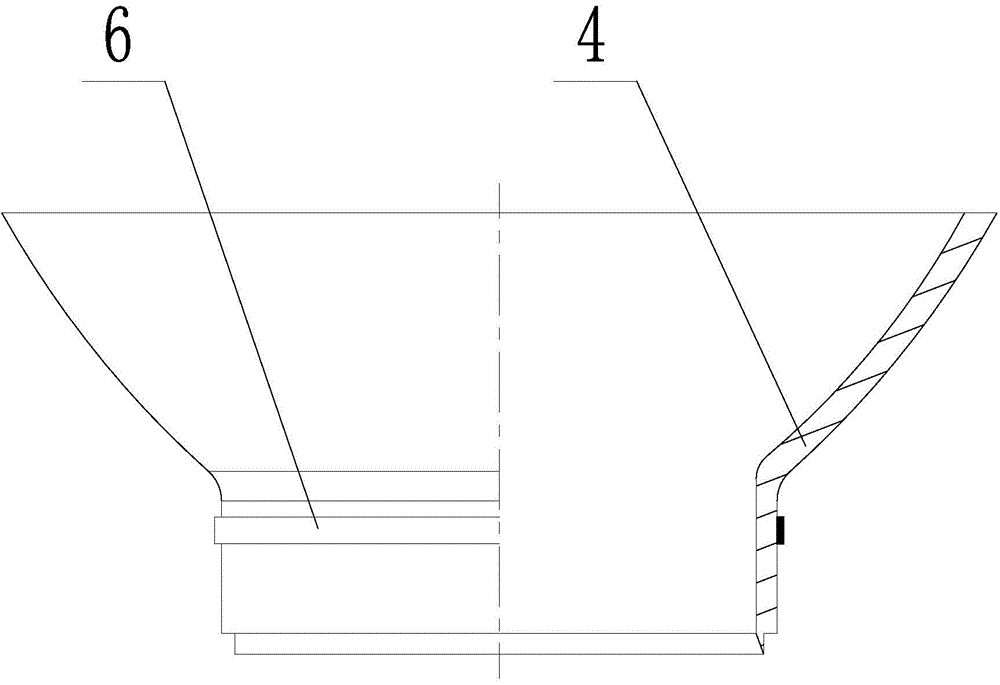
[0033] The vortex, the front part of the cylinder and the sleeve of the head assembly of the flame tube are nickel-based superalloys of GH3536, and the splash plate is a nickel-based superalloy of GH5188. The front part of the cylinder, the splash plate, the sleeve and the vortex are to be welded The axial overlapping assembly dimensions of the cylinder are 3.0mm, 3.5mm, and 4.0mm respectively. The theoretical diameters of the front section of the cylinder, the splash plate, and the sleeve located at the vortex to be welded are φ45mm, φ30mm, and φ22mm. Each brazing batch There are process test pieces in the flame tube head assembly of the second time, and the brazing process is carried out together with the flame tube head assembly as a part, and the process test piece is used for the final quality inspection.
[0034] The type of vacuum furnace used in the brazing process is VBFV-160, the working temperature of the equipment is 550-1300°C, the temperature uniformity is ±5°C, a...
Embodiment 2
[0051] The vortex, the front part of the cylinder and the sleeve of the head assembly of the flame tube are nickel-based superalloys of GH3536, and the splash plate is a nickel-based superalloy of GH5188. The front part of the cylinder, the splash plate, the sleeve and the vortex are to be welded The axial overlapping assembly dimensions are 3.5mm, 4.5mm, and 6mm respectively. The theoretical diameters of the front section of the cylinder, the splash plate, and the sleeve located at the vortexer to be welded are φ50mm, φ35mm, and φ25mm. Each brazing batch There are process test pieces in the flame tube head assembly, which are brazed together with the flame tube head assembly as a part, and the process test piece is used for final quality inspection.
[0052] The type of vacuum furnace used in the brazing process is VBFV-160, the working temperature of the equipment is 550-1300°C, the temperature uniformity is ±5°C, and the ultimate vacuum pressure is 0.001Pa.
[0053] The bra...
PUM
| Property | Measurement | Unit |
|---|---|---|
| Thickness | aaaaa | aaaaa |
| Length | aaaaa | aaaaa |
| Width | aaaaa | aaaaa |
Abstract
Description
Claims
Application Information