Supercharge Your Innovation With Domain-Expert AI Agents!

Argon-arc welding fixture for T-shaped components

A technology of argon arc welding and parts, applied in the field of argon arc welding fixtures of T-shaped parts, can solve the problems of high cost, affecting material performance, high hardness, etc., achieve the effect of protecting material performance and overcoming the increase in hardness and strength of weld metal

Active Publication Date: 2015-04-01
JIANGXI HONGDU AVIATION IND GRP
View PDF6 Cites 0 Cited by
  • Summary
  • Abstract
  • Description
  • Claims
  • Application Information

AI Technical Summary

Problems solved by technology

Now processing T-shaped parts can be processed by milling and welding processes, but because some metal materials have the characteristics of high strength, high hardness, and high cost, they have higher requirements for milling and cutting processes, and it is easy to cause waste of materials
For processing T-shaped parts by welding process, ordinary T-shaped argon arc welding fixtures are mostly used now, but the heat-affected zone of the weld seam is completely exposed to the air during welding. Since welding will generate high temperature in the heat-affected zone of the weld seam, the material surface contacts Air will oxidize rapidly, affecting material properties

Method used


Image

  • Argon-arc welding fixture for T-shaped components
  • Argon-arc welding fixture for T-shaped components
  • Argon-arc welding fixture for T-shaped components

Examples


Embodiment

[0014] Example: see figure 1 , figure 2 , image 3 .

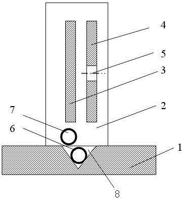
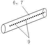
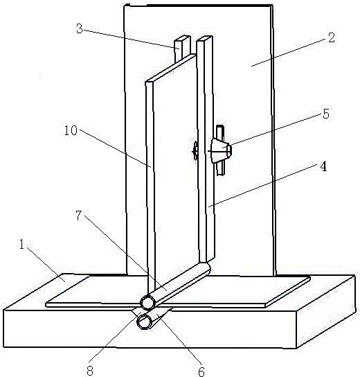
[0015] A T-shaped part argon arc welding fixture, including a column plate 2, a base plate 1, two positioning baffles 3, 4, divided into two left and right pieces, two air guide pipes 6, 7, the column plate 2 is perpendicular to the base plate 1, the left and right positioning blocks 3 and 4 are installed vertically on the column plate 2 to fix the T-shaped part 10, the two air guide pipes 6 and 7 are perpendicular to the column plate 2, and the first air guide pipe 6 is arranged At the lower part of the T-shaped part 10 , the second air guide pipe 7 is arranged at the vertical angle position of the T-shaped part 10 .

[0016] Grooves 8 are formed on the bottom plate 1 at positions corresponding to the two positioning baffles 6 and 7 , and the first air guide pipe 6 is arranged in the grooves 8 .

[0017] Right locating baffle 4 is fixed on the left locating baffle 3 by T-shaped part 10 by jacking bolt 5 that is insta...


PUM


Abstract

The invention relates to the field of argon-arc welding, in particular to an argon-arc welding fixture for T-shaped components. The argon-arc welding fixture for the T-shaped components comprises an upright column plate, a bottom plate, a left positioning barrier, a right positioning barrier and two gas guide pipelines. The upright column plate is perpendicularly arranged on the bottom plate, the left positioning barrier and the right positioning barrier are perpendicularly mounted on the upright column plate and are used for fixing a T-shaped component, the two gas guide pipelines are perpendicular to the upright column plate, the first gas guide pipeline is arranged on the lower portion of the T-shaped component, and the second gas guide pipeline is arranged at a position of a perpendicular included angle of the T-shaped component. A groove is formed in the bottom plate and corresponds to the positioning barriers, and the first gas guide pipeline is arranged in the groove. The T-shaped component is fixed onto the left positioning barrier by the aid of the right positioning barrier via a puller bolt which is mounted on the right positioning barrier. A plurality of gas holes are formed in the two gas guide pipelines. The argon-arc welding fixture has the advantages that the argon-arc welding fixture can be filled with argon via weld heat-affected zones, so that the shortcoming of quick oxidation of the surfaces of materials due to the fact that the surfaces of the materials are in contact with the air during hot processing can be overcome, and the performance of materials can be protected after the materials are subjected to hot processing.

Description

technical field [0001] The invention relates to the field of argon arc welding, in particular to a fixture for argon arc welding of T-shaped parts. Background technique [0002] Some metals will be oxidized when the temperature exceeds a certain temperature during thermal processing, which will increase the hardness and strength of the weld metal, while the plasticity will drop sharply, such as titanium alloy parts. Now T-shaped parts can be processed by milling and welding processes, but because some metal materials have the characteristics of high strength, high hardness, and high cost, they have higher requirements for milling and cutting processes, and it is easy to cause waste of materials. For processing T-shaped parts by welding process, ordinary T-shaped argon arc welding fixtures are mostly used now, but the heat-affected zone of the weld seam is completely exposed to the air during welding. Since welding will generate high temperature in the heat-affected zone of t...

Claims


Application Information

Patent Timeline
IPC IPC(8): B23K9/32B23K9/16
CPCB23K9/16B23K9/32B23K37/0443
Inventor 魏娜陈辉毛萍萍万里鹏王云飞李燕平李旭勇高翔
Owner JIANGXI HONGDU AVIATION IND GRP
Features
  • R&D
  • Intellectual Property
  • Life Sciences
  • Materials
  • Tech Scout
  • Unparalleled Data Quality
  • Higher Quality Content
  • 60% Fewer Hallucinations
Learn More