An oil shale gas heat carrier carbonization furnace that is easy to be enlarged

A technology of gas heat carrier and carbonization furnace, which is applied in the field of oil shale carbonization furnace, can solve the problems of insufficient material utilization efficiency, low calorific value of outlet gas, and environmental pollution, so as to solve the problems of coking and incomplete carbonization, and improve output The effect of improving the oil rate and improving the efficiency of dry distillation

Active Publication Date: 2016-09-28
NORTHEAST DIANLI UNIVERSITY
View PDF12 Cites 0 Cited by
  • Summary
  • Abstract
  • Description
  • Claims
  • Application Information

AI Technical Summary

Problems solved by technology

The third type is the Maoming retort furnace, which has a square structure and is an internal combustion furnace. It is not equipped with a heating furnace, and the heat transfer method is convective heat transfer.
When the gas burns in the furnace, it produces high-temperature flue gas of about 1000°C, which often causes coking in the furnace and is forced to stop the furnace for cleaning. Mixing results in lower calorific value
Among them, both the Fushun type retort furnace and the Maoming type retort furnace have defects such as low oil recovery and environmental pollution. In particular, the Maoming type retort furnace was completely discontinued in the 1980s due to pollution problems; It essentially improves the oil recovery rate of the carbonization furnace and reduces the pollution problem, but because of its own structural limitations, its utilization efficiency of materials is still not high enough

Method used


Image

  • An oil shale gas heat carrier carbonization furnace that is easy to be enlarged
  • An oil shale gas heat carrier carbonization furnace that is easy to be enlarged
  • An oil shale gas heat carrier carbonization furnace that is easy to be enlarged

Examples


Embodiment Construction

[0017] The following structural drawings and embodiments further describe the present invention:

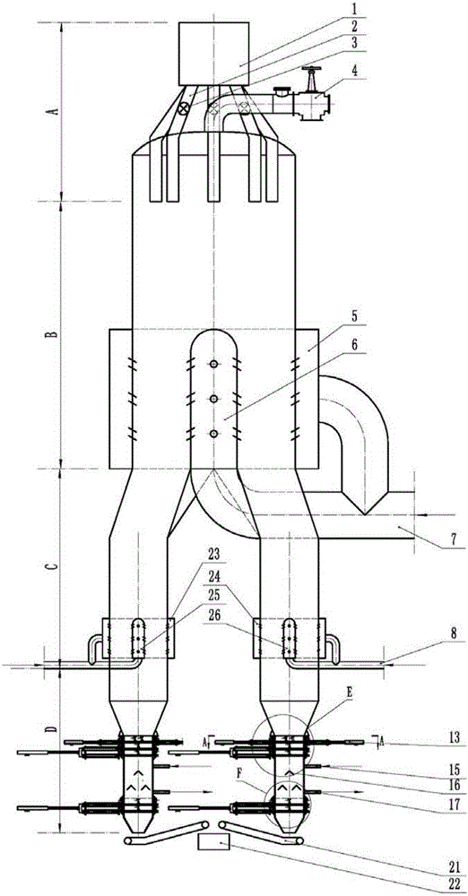
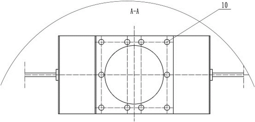
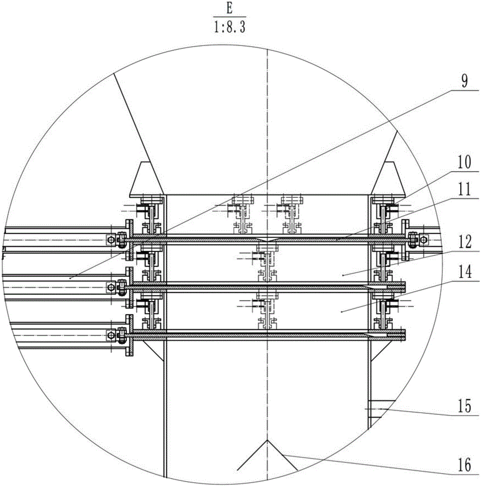
[0018] see Figure 1-Figure 4 , an oil shale gas heat carrier retort furnace that is easy to be enlarged in the present invention includes a furnace body, and the furnace body is composed of a feed section A, a retort section B, a cooling section C and a dry slagging system arranged in sequence from top to bottom D composition, a hopper 1 is set on the top of the furnace body where the feed section A of the furnace body is located, and the hopper 1 is connected with a distributor 2 that extends into the furnace body through a star valve 3 and has several distribution pipes. Oil and gas outlet 4, a sealed first air distribution bellows 5 is provided on the furnace body where the retort section B is located, and a first hood-type air distribution device connected to the first air distribution bellows 5 is provided in the furnace body where the retort section B is located 6. The fi...


PUM


Abstract

The invention discloses a dry distillation furnace for oil shale gas heat carriers easy for enlargement. The dry distillation furnace is characterized by comprising the following steps: feeding crushed oil shale materials in required particle sizes into a dry distillation segment at the constant speed under the control of a feeding controller; ensuring that the hot mine gas of 600-700 DEG C pumped in can be in intensive mixing dry distillation with the materials under the combined action of a gas distribution bellow and a cap-type gas distribution device in the dry distillation segment; arranging a gas distribution bellow and a cap-type gas distribution device in a cooling segment as well, guaranteeing that the cold mine gas of 20-40 DEG C pumped in can be in intensive mixing with carbocoal to be cooled, and cooling carbocoal to below 300 DEG C; in a dry slag discharge system, adopting a labyrinth sealing plate structure and a cold mine gas circulation system in a carbocoal discharge chamber to guarantee that carbocoal is discharged smoothly, and that outside air is prevented from entering a furnace body meanwhile; meanwhile, array umbrellas are arranged in the carbocoal discharge chamber to prevent carbocoal from impacting a lower sealing plate in the falling process; after being discharged, carbocoal is conveyed into a crush machine through a sealing belt conveyor for crushing treatment.

Description

technical field [0001] The invention relates to an oil shale retort furnace, in particular, an oil shale retort furnace gas heat carrier retort furnace which is easy to be large-scale, and is suitable for retort oil shale under the gas full cycle state where gas is used as the gas heat carrier . Background technique [0002] There are three kinds of retort furnaces that are widely used in the existing medium and low temperature oil shale retort refining. The first one is the Fushun type retort furnace. For coordination, the heat transfer method is convective heat transfer. When working, a blower is used to send saturated combustion-supporting air from the bottom of the retort furnace, and the fixed carbon in the material is burned to generate flue gas to carry out retort on the upper oil shale. The regenerative heating furnace is heated to 550~650℃ for adjustment, the oil recovery rate is 60~65%, the particle size of the treated material is 12~75mm, and the processing capa...

Claims


Application Information

Patent Timeline
Patent Type & Authority Patents(China)
IPC IPC(8): C10B53/06C10B49/02
CPCC10B49/02C10B53/06
Inventor 王擎华泽嘉柏静儒贾春霞刘洪鹏秦宏
Owner NORTHEAST DIANLI UNIVERSITY
Why Eureka
Try Eureka