
Low-alloy high-strength high-toughness steel plate and manufacturing method thereof

A high-strength, high-toughness, manufacturing method technology, applied in manufacturing tools, metal rolling, metal rolling, etc., can solve the problems of poor welding performance and machinability, poor internal quality, long production process, etc., and achieve machinability. Excellent results, uniform internal composition of the slab, and good surface quality

Inactive Publication Date: 2015-04-01
BAOSHAN IRON & STEEL CO LTD
View PDF5 Cites 51 Cited by
  • Summary
  • Abstract
  • Description
  • Claims
  • Application Information

AI Technical Summary

Problems solved by technology

For industrial production, continuous casting is generally used to produce continuous casting slabs, and then steel plates of a certain thickness are obtained by rolling. Generally, the thickness of continuous casting slabs is 200-300mm, and the large-thickness, high-strength hardness steel plates often have core quality. It is difficult to ensure that it is difficult to fully meet the needs of working conditions; casting castings have the disadvantages of high alloy content, poor internal quality, and easy cracking during use, which greatly reduces the service life of the product; using die casting production, although It can produce large-thickness steel plates, but it has disadvantages such as long production process, low yield and high production cost, which is not conducive to product marketing
[0003] Chinese patent CN1140205A discloses a medium-high-carbon medium-alloy wear-resistant steel, which is produced by a casting process, and its carbon and alloy elements (Cr, Mo, etc.) content are relatively high, which will inevitably lead to poor welding performance and machining performance, and a long service life. Low

Method used


Image

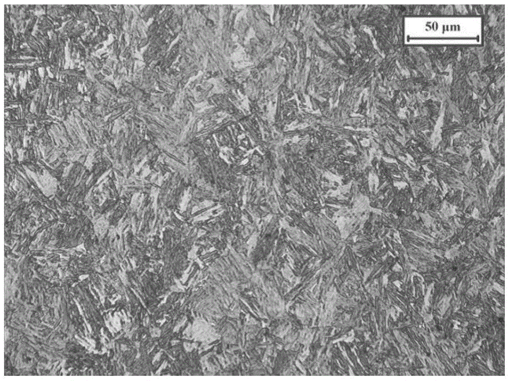
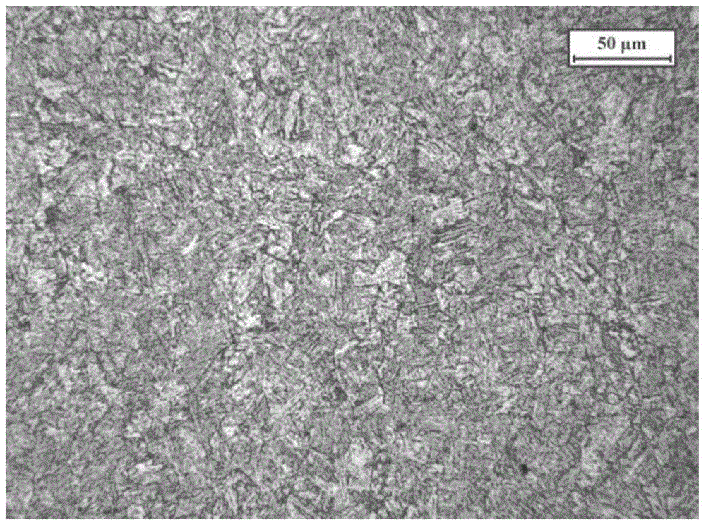
  • Low-alloy high-strength high-toughness steel plate and manufacturing method thereof
  • Low-alloy high-strength high-toughness steel plate and manufacturing method thereof
  • Low-alloy high-strength high-toughness steel plate and manufacturing method thereof

Examples


Embodiment Construction

[0053] The present invention will be further described below in conjunction with embodiment.

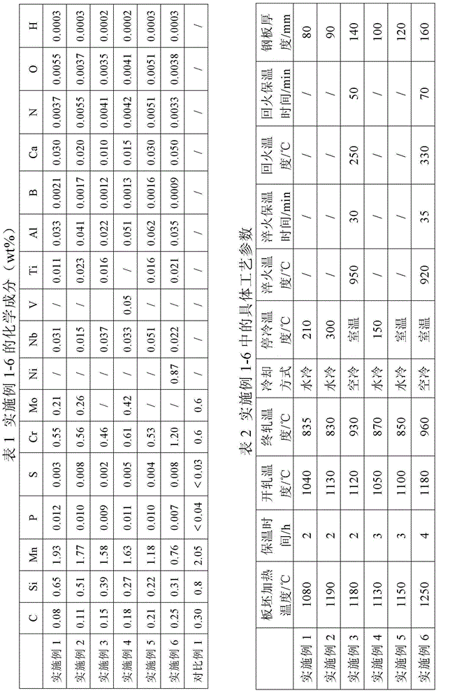
[0054] Table 1 shows the chemical composition of the steel plates of Examples 1-6 and Comparative Example 1 of the present invention, the specific process parameters are shown in Table 2, and the mechanical properties are shown in Table 3.

[0055] The manufacturing method of the steel plates of Examples 1-6 and Comparative Example 1 (Comparative Example 1 is Example 2 in the patent CN1865481A) is as follows: the corresponding smelting raw materials are followed in turn by the following steps: smelting→casting→compounding→heating→rolling Manufacturing → cooling directly after rolling, or smelting → casting → compounding → heating → rolling → quenchingtempering.

[0056] It can be seen from Table 3 that the Brinell hardness of the steel plate of the present invention is 390-460HB, yield strength: 900-1100MPa, tensile strength: 1100-1400MPa, elongation: 11-15%, and Charpy V-type lon...


PUM


Abstract

The invention relates to a low-alloy high-strength high-toughness steel plate and a manufacturing method thereof. The low-alloy high-strength high-toughness steel plate comprises the following components in percentage by mass: 0.08-0.25% of C, 0.10-1.00% of Si, 0.50-2.00% of Mn, less than 0.020% of P, less than 0.010% of S, 0.10-2.00% of Cr, 0-1.00% of Mo, 0-2.00% of Ni, 0.010-0.080% of Nb, at most 0.10% of V, at most 0.060% of Ti, 0.0005-0.0040% of B, 0.010-0.080% of Al, 0.010-0.080% of Ca, at most 0.0080% of N, at most 0.0080% of O, at most 0.0004% of H, and the balance of Fe and inevitable impurities. 0.20%<=(Cr / 5+Mn / 6+50B)<=0.55%, 0.02%<=(Mo / 3+Ni / 5+2Nb)<=0.45%, and 0.01%<=(Al+Ti)<=0.13%. The Brinell Hardness of the steel plate is 390-460 HB, the yield strength is 900-1100 MPa, the tensile strength is 1100-1400 MPa, the elongation percentage is 11-15%, the -40 DEG C Charpy V-notch longitudinal impact work is greater than or equal to 40J, and the plate thickness can reach 100mm above. Thus, the steel plate implements matching of high strength, high hardness and high toughness, and has favorable machining properties.

Description

technical field [0001] The invention belongs to the technical field of metallurgy, and in particular relates to a low-alloy, high-strength, high-toughness steel plate and a manufacturing method thereof. Background technique [0002] Mechanical equipment such as engineering, mining, and metallurgy usually require steel plates with high strength, high hardness, and high toughness, such as parts of bulldozers, excavators, and scraper conveyors. At the same time, special equipment such as large crushers and large excavators require large-thickness steel plates, and the thickness can reach more than 100mm. For industrial production, continuous casting is generally used to produce continuous casting slabs, and then steel plates of a certain thickness are obtained by rolling. Generally, the thickness of continuous casting slabs is 200-300 mm, and the large-thickness, high-strength hardness steel plates often have core quality. It is difficult to guarantee that it is difficult to f...

Claims


Application Information

Patent Timeline
IPC IPC(8): C22C38/58C22C38/54C22C38/38C22C38/32C21D8/02B22D11/00
CPCC21D8/0226C21D8/0247C22C38/001C22C38/002C22C38/02C22C38/04C22C38/18C22C38/22C22C38/26C22C38/28C22C38/32C22C38/38C22C38/40C22C38/44C22C38/48C22C38/50C22C38/54C22C38/58B21B15/0085C21D8/0263C21D1/18C21D1/25C22C38/06C22C38/24B21B2001/228C21D2211/001C21D2211/008
Inventor 袁向前李红斌焦四海姚连登
Owner BAOSHAN IRON & STEEL CO LTD
Learn More