Method for producing metallic iron

A manufacturing method and technology of metallic iron, applied in the field of metallic iron, can solve the problems that the separation between metallic iron and slag has not been studied.

Inactive Publication Date: 2015-04-08
KOBE STEEL LTD
View PDF13 Cites 7 Cited by
  • Summary
  • Abstract
  • Description
  • Claims
  • Application Information

AI Technical Summary

Problems solved by technology

However, no research has been conducted on improving the separation of metallic iron and slag

Method used


Image

  • Method for producing metallic iron
  • Method for producing metallic iron
  • Method for producing metallic iron

Examples


change example 1

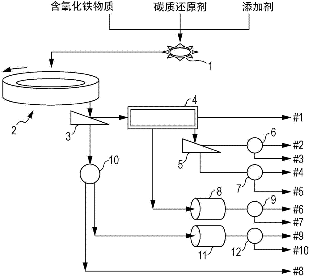
[0436] When the agglomerate is heated in a moving hearth type heating furnace, the metallic iron is melted on the hearth and coalesced with adjacent metallic iron to coarsen. Similarly, the slag melts and coalesces with neighboring slag and coarsens. The coarsened slag is crushed and made finer when discharged from the heating furnace or by subsequent treatment, and the coarsened metallic iron remains in a coarse state without being made finer. When the coarsened metallic iron is supplied to the crushing process, a load is applied to the crusher, and the consumption of the crusher is severe.

[0437] Therefore, in Modification 1, such as Figure 3-3 As shown, a sieve c ( Figure 3-3 105) for sieving. Then, the coarse particles remaining on the sieve c (on-sieve c) are supplied to the crusher 102, and crushed by impacting on the crusher 102 .

change example 2

[0439] When the agglomerate is heated at 1300°C or higher in a heating furnace, a bottom layer of material such as carbonaceous particles and refractory particles is laid to protect the hearth of the heating furnace. The particle size of the bottom charge is preferably small particles with a particle diameter of 0.5-3 mm. The bottom charge is discharged from the heating furnace together with the reduced material after the agglomerate is heated. Therefore, through the above-mentioned sieving step c, the bottom charge is included in the medium and fine particles (substances under the sieve c) that pass through the sieve c.

[0440] Therefore, in Modification 2, such as Figure 3-3 As shown, a sieve c ( Figure 3-3 105) for sieving, and for the medium and fine particles (substances under sieve c) passing through the sieve c, use a sieve b with a mesh size of 2 to 8 mm ( Figure 3-3 106) Sieving. The reason why the mesh of the sieve b used in the screening step b is 2 to 8 mm ...

change example 3

[0442] In modification example 3, as mentioned above, also can use magnetic separator ( Figure 3-3 107b) After sorting, it is supplied to the crusher 102 through a path not shown in the figure, and impacts are applied to the magnetic objects to crush them. By pre-separating nonmagnetic substances with a magnetic separator, the recovery efficiency of metallic iron obtained by crushing magnetic substances can be improved.

[0443] In addition, the medium particles recovered as the under-sieve c and the over-sieve b with a magnetic separator ( Figure 3-3 107b) After sorting, the magnetic material is supplied to the pulverizer ( Figure 3-3 108b) and pulverized, with a magnetic separator ( Figure 3-3 107e) of non-magnetic matter is sorted in advance, thus also can improve the metallic iron ( Figure 3-3 104b) Recovery efficiency.


PUM

PropertyMeasurementUnit
particle sizeaaaaaaaaaa
particle diameteraaaaaaaaaa

Abstract

The first purpose of the present invention is to provide a method for producing metallic iron, whereby, in the production of metallic iron by heating an agglomerate, which comprises an iron oxide-containing material and a carbonaceous reducing agent, in a movable hearth type heating furnace, metallic iron can be efficiently collected from a reduced product containing metallic iron and a slag, said reduced product being obtained by heating the agglomerate. The method for producing metallic iron according to the first embodiment of the present invention comprises: a step for forming an agglomerate of a mixture which comprises an iron oxide-containing material and a carbonaceous reducing agent; a step for introducing the obtained agglomerate into a movable hearth type heating furnace and reducing the same by heating; a step for milling a reduced product containing metallic iron and a slag, said reduced product being discharged from the movable hearth type heating furnace, using an impact mill; and a step for selecting and collecting the metallic iron using a separator.

Description

technical field [0001] The present invention relates to a method for producing metallic iron by heating an agglomerated agglomerate containing a mixture of a substance containing iron oxide and a carbonaceous reducing agent by using a moving hearth type heating furnace. Background technique [0002] Methods of producing metallic iron from iron oxide-containing substances such as iron ore are classified into several types according to methods of separating gangue components in iron oxide-containing substances. [0003] The method that can produce the largest amount of metallic iron is the integrated ironmaking method using a blast furnace. This method uses high-grade iron ore with few gangue components, or iron oxide-containing substances composed of iron ore whose iron grade has been improved through ore dressing, and is heated in a blast furnace and reduced to melt. Next, it is separated into gangue components and milling iron (carbon-saturated iron) to produce metallic ir...

Claims


Application Information

Patent Timeline
Patent Type & Authority Applications(China)
IPC IPC(8): C21B13/10C21B11/08C22B1/244C22B5/10
CPCC22B1/245C21B11/08C21B13/0086C21B13/0046C21B13/105C21B13/14B03C1/02B03C1/30B03C2201/20B07B15/00C22B1/2406Y02P10/20C21B13/10
Inventor 杉山健原田孝夫椎野纯一三村毅饭岛胜之冈高宪
Owner KOBE STEEL LTD
Why Eureka
Try Eureka