A catalytic cracking method and device

A catalytic cracking and catalyst regeneration technology, applied in catalytic cracking, chemical instruments and methods, cracking and other directions, can solve the problems of short oil agent contact time, reduce the temperature of the regenerated catalyst, and adjust the inflexibility, etc., and achieve the short oil agent contact time, The effect of improving properties

Active Publication Date: 2016-06-08
SINOPEC LUOYANG PETROCHEM ENG CORP +1
View PDF9 Cites 0 Cited by
  • Summary
  • Abstract
  • Description
  • Claims
  • Application Information

AI Technical Summary

Problems solved by technology

[0007] The purpose of the present invention is to provide a kind of catalytic cracking method and device, to solve the existing catalytic cracking technology to reduce the regenerated catalyst temperature and improve the measures of heavy oil riser agent oil ratio narrow scope of application (not suitable for single riser catalytic cracking unit or only applicable to catalytic cracking units with excess heat), the adjustment is not flexible enough (using the main air to cool the regenerated catalyst due to the limitation of the cooling main air volume, so that the cooling effect is affected, or through the light hydrocarbon standby catalyst or external extraction The regenerated catalyst after cooling by the heater directly participates in the catalytic cracking reaction of heavy oil to increase the agent-oil ratio of heavy oil riser due to the limited flow rate of the two catalysts, which limits the increase of the agent-oil ratio of heavy oil riser), and participates in the catalytic cracking reaction of heavy oil low catalyst activity (affected by the mixing of light hydrocarbons) and difficulty in achieving shorter oil contact time

Method used

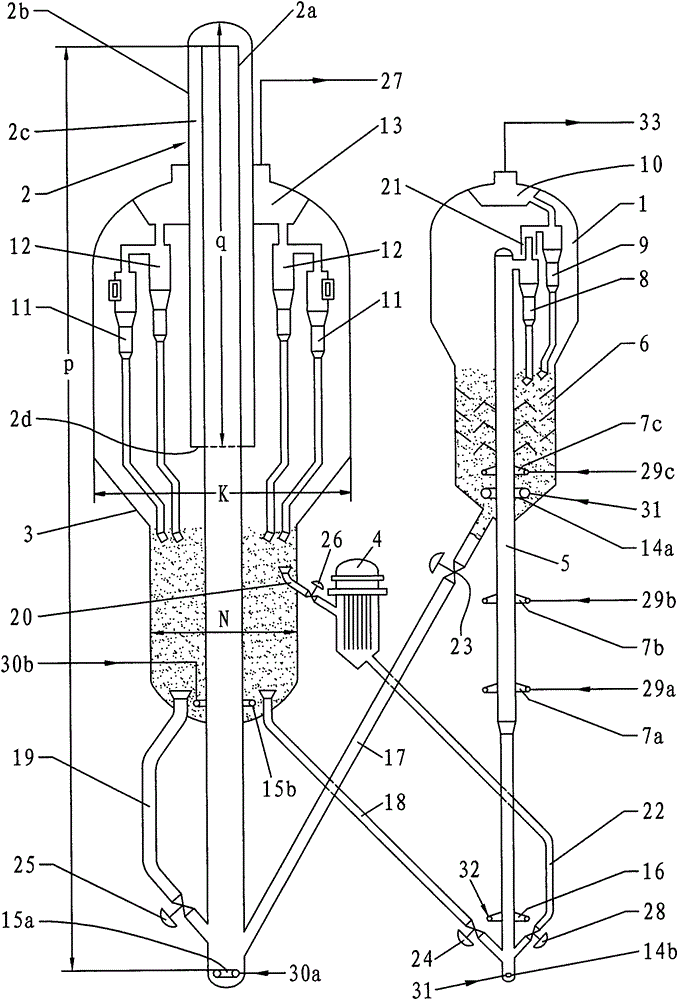
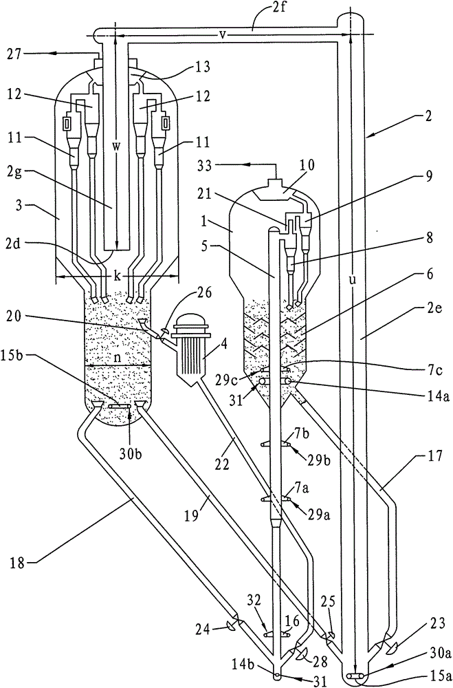

Image

  • A catalytic cracking method and device
  • A catalytic cracking method and device
  • A catalytic cracking method and device

Examples


Embodiment 1

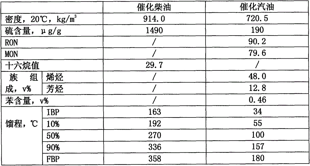
[0068] The main operating conditions and product distribution of Examples 1-5 are shown in Table 4. The main properties of the liquid product of Example 1 are shown in Table 5, the main properties of the liquid product of Example 2 are shown in Table 6, the main properties of the liquid product of Example 3 are shown in Table 7, and the main properties of the liquid product of Example 4 are shown in Table 8. The main properties of liquid products of 5 are shown in Table 9.

[0069] Table 1 Heavy oil raw material properties (comparative example, embodiment 1~5)

[0070] Heavy Oil Raw Materials

Daqing Atmospheric Residue

Density (20℃), kg·m -3

900.2

Charcoal residue, %

4.2

Family composition, %

saturated hydrocarbon

62.3

Aromatics

22.6

Colloid + asphaltenes

15.1

Sulfur content, μg g -1

1450

Ni, μg g -1

4.3

V, μg·g -1

0.2

[0071] The main operating c...


PUM

PropertyMeasurementUnit
lengthaaaaaaaaaa
lengthaaaaaaaaaa

Abstract

The invention discloses a catalytic cracking method and device in petroleum chemical industry. The catalytic cracking method is as follows: performing heavy oil catalytic cracking reaction with the oil agent contact time of 0.2-1.5s by use of a lift pipe; performing gas-solid separation on a reaction material flow by use of a cyclone separator; entering reaction oil and gas into a fractionating tower for fractional distillation; after steam stripping of a spent catalyst, entering the spent catalyst into a baffle tubular regenerator, after mixing with a uncooled cycle regenerated catalyst, burning off more than 90% of generated coke by main air co-current contact with the baffle tubular regenerator, entering a semi regenerated catalyst into a turbulent bed regenerator, burning off the rest generated coke by main air countercurrent contact with the turbulent bed regenerator, and returning the regenerated catalyst into the lift pipe for recycling use. The invention discloses a catalytic cracking device for realizing the catalytic cracking method. The catalytic cracking method and device can be used for heavy oil catalytic cracking.

Description

technical field [0001] The invention relates to a catalytic cracking method and device in the petrochemical industry. Background technique [0002] At present, the conventional catalytic cracking units used in the petrochemical industry generally have the following disadvantages: First, due to the limitation of regeneration kinetics, the regeneration temperature is relatively high, resulting in a relatively high temperature of the regenerated catalyst participating in the reaction (generally around 700°C) ;Limited by the heat balance of the device, the agent-oil ratio of the heavy oil riser is relatively small, generally the total agent-oil ratio is 5-8 (the total agent-oil ratio of the riser is the weight circulation of the catalyst in the riser and the feed of each strand of the riser The ratio of the sum of the weight flow rates), so that the number of active sites contacted by the unit weight of heavy oil feed is less, which inhibits the catalytic cracking reaction to a ...

Claims


Application Information

Patent Timeline
Patent Type & Authority Patents(China)
IPC IPC(8): C10G11/18B01J8/26
CPCB01J8/26C10G11/18C10G11/182
Inventor 陈曼桥武立宪王文柯张亚西樊麦跃汤海涛
Owner SINOPEC LUOYANG PETROCHEM ENG CORP
Why Eureka
Try Eureka