Ultrasonic assisted powder injection molding device and method

A powder injection molding, ultrasonic-assisted technology, used in ceramic molding machines, manufacturing tools, etc., can solve the problems of high-load feeding with high viscosity, difficult to inject, difficult to inject, and uneven feeding, etc., to improve the filling performance. and product surface quality, reducing melt viscosity, simple and easy-to-operate device

Active Publication Date: 2015-04-22
SOUTH UNIVERSITY OF SCIENCE AND TECHNOLOGY OF CHINA
View PDF9 Cites 16 Cited by
  • Summary
  • Abstract
  • Description
  • Claims
  • Application Information

AI Technical Summary

Problems solved by technology

[0006] The invention solves the technical problems that in the field of metal or ceramic powder injection molding, it is easy to agglomerate during the mixing preparation process, the feeding is uneven, and the high-load feeding is difficult to inject due to high v

Method used


Image

  • Ultrasonic assisted powder injection molding device and method
  • Ultrasonic assisted powder injection molding device and method
  • Ultrasonic assisted powder injection molding device and method

Examples


Embodiment 1

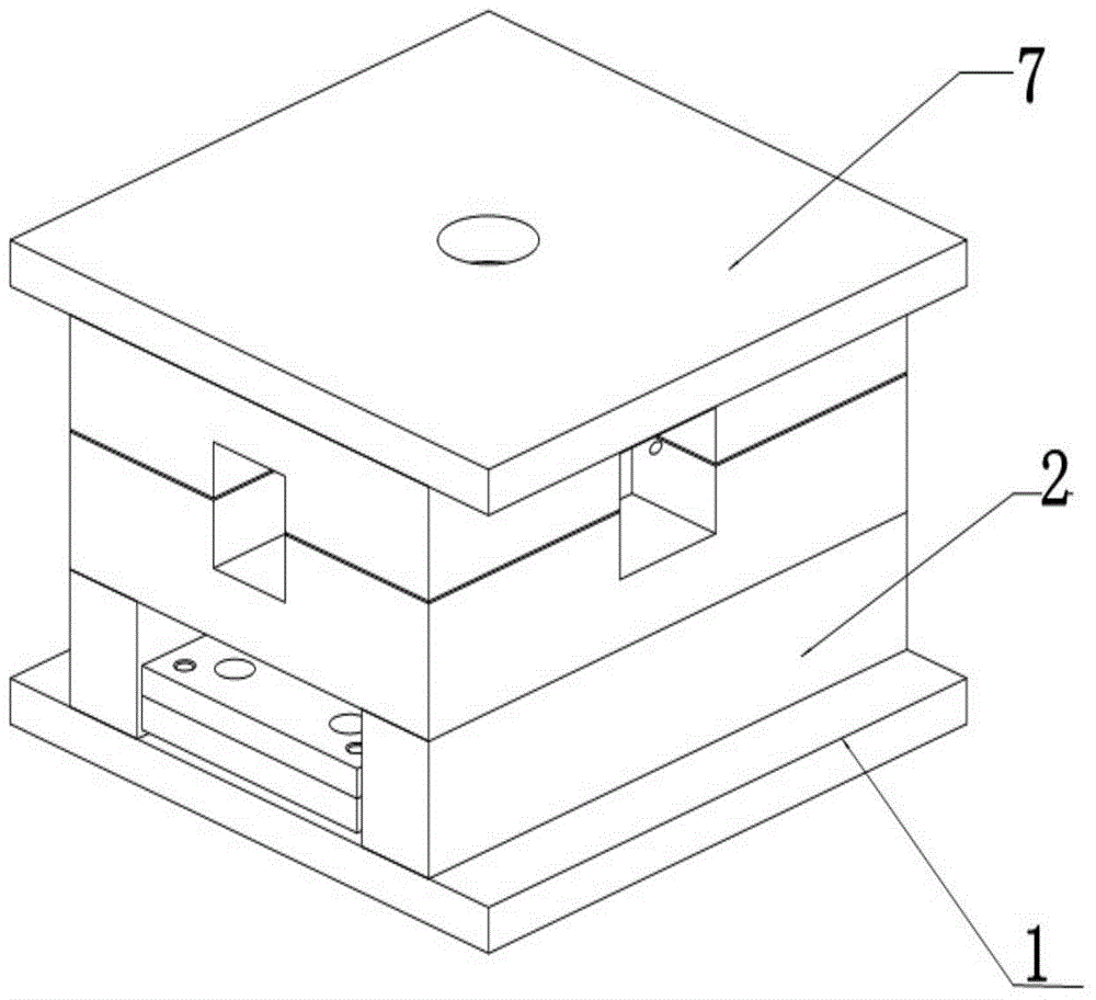
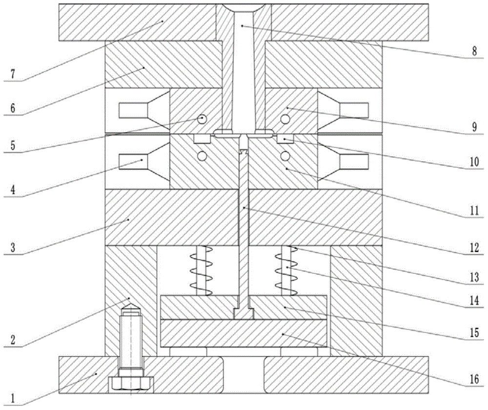
[0045] The ultrasonic-assisted powder injection molding device described in this embodiment includes a banburying device and an injection molding device.

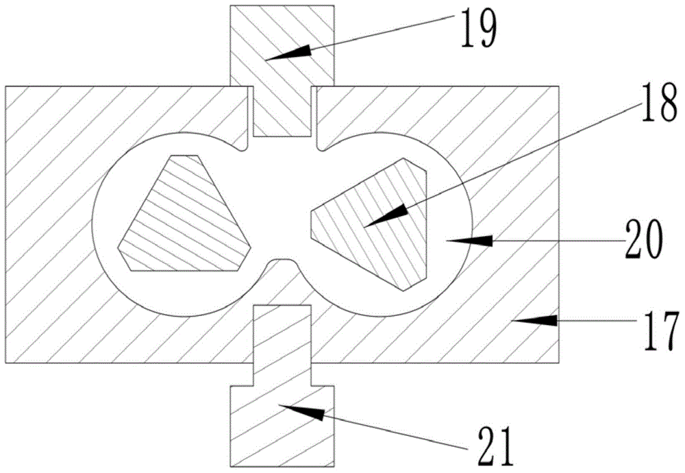
[0046] Wherein, the banburying device 17 is a common mixing equipment in the field, and the metal powder and the binder are mixed in this equipment. Such as figure 1 As shown, inside the shell of the banburying device 17, there is a banburying chamber 20 for containing the mixed materials, and the surface of the shell is provided with a material port communicating with the banburying chamber 20; the rotor 18 is placed in the banburying chamber of the banburying device In the chamber 20, a weight 19 is arranged at the material opening, and the weight 19 is suitable for sealing the material opening. The binder and powder are added into the banburying chamber 20 of the banburying device through the feed port in a certain proportion and in a certain order, and the weight 19 is pressed down at the feed port to seal, and the r...

Embodiment 2

[0061] The ultrasonic-assisted powder injection molding device described in this embodiment includes a banburying device and an injection molding device.

[0062] Such as figure 1 As shown, inside the shell of the banburying device 17, there is a banburying chamber 20 for containing the mixed materials, and the surface of the shell is provided with a material port communicating with the banburying chamber 20; the rotor 18 is placed in the banburying chamber of the banburying device In the chamber 20, a weight 19 is arranged at the material opening, and the weight 19 is suitable for sealing the material opening. The binder and powder are added into the banburying chamber 20 of the banburying device through the feed port in a certain proportion and in a certain order, and the weight 19 is pressed down at the feed port to seal, and the rotor 18 is rotated for mixing.

[0063] In this embodiment, two first transducers are symmetrically arranged at 8 mm to the left and right of...


PUM


Abstract

The invention relates to an ultrasonic assisted powder injection molding device and method. The device comprises an internal mixing device and an injection molding device. An internal mixing cavity is formed inside a shell of the internal mixing device, and a feeding hole communicated with the internal mixing cavity is formed in the surface of the shell. A rotor is arranged in the internal mixing cavity of the internal mixing device. A pressing weight is arranged at the feeding hole and is suitable for sealing the feeding hole. The injection molding device comprises a threaded rod injection molding machine and an injection mold. The feedstock obtained by internal mixing through the internal mixing device is injected into the injection mold through the threaded rod injection molding machine, and blanks are obtained by molding. A first energy converter is connected with the internal mixing device, and a second energy converter is connected with the injection mold. The first energy converter and the second energy converter are connected with an ultrasonic generator respectively, and are suitable for driving the internal mixing device and the injection mold respectively for supersonic vibration. The ultrasonic assisted powder injection molding device and method can effectively remove the agglomeration phenomenon in the mixing process and lower the mixing temperature, and are especially suitable for the feedstock made of metal or ceramic powder, of irregular shapes or high-carrying capacity, which is hard to inject.

Description

technical field [0001] The invention relates to a powder injection molding device and method, in particular to an ultrasonic-assisted metal or ceramic powder injection molding device and method. Background technique [0002] Powder injection molding technology is a new type of powder metallurgy near net forming technology formed by introducing modern plastic injection molding technology into the field of powder metallurgy. It combines the advantages of powder metallurgy and plastic injection molding technology, and breaks through the traditional metal powder molding The shape of the product is limited by the forming process. At the same time, it can form three-dimensional parts with complex shapes in large quantities and with high efficiency. It has incomparable advantages over conventional powder metallurgy, precision machining and precision casting. It can produce plastic products just like plastic products. Metal and ceramic parts with complex shapes can be produced by on...

Claims


Application Information

Patent Timeline
IPC IPC(8): B22F3/22B28B1/24
Inventor 余鹏吕永虎叶曙龙莫畏郝华丽
Owner SOUTH UNIVERSITY OF SCIENCE AND TECHNOLOGY OF CHINA
Why Eureka
Try Eureka