Synchronous rectification drive circuit and synchronous rectification method of switching power supply

A synchronous rectification, switching power supply technology, applied in the direction of converting AC power input to DC power output, electrical components, output power conversion devices, etc., can solve the problems of large driving loss, difficult application, application, etc. Small, drive loss reduction effect

Active Publication Date: 2015-04-22
MORNSUN GUANGZHOU SCI & TECH
View PDF4 Cites 7 Cited by
  • Summary
  • Abstract
  • Description
  • Claims
  • Application Information

AI Technical Summary

Problems solved by technology

[0004] 1. Synchronous rectification drive waveform has negative voltage, resulting in large drive loss
[0005] 2. The synchronous rectification drive waveform negative voltage is proportional to the input voltage of the switching power supply, and the Vgs voltage of the general MOS tube is only ±20V, so the switching power supply in a wide input voltage range cannot be applied; while in the application field of the module power supply, the input voltage The range has 2:1 input voltage range and 4:1 input voltage range, this circuit cannot be applied in the 4:1 input voltage range
[0006] like figure 2 Shown is another synchronous rectification isolation drive technology in the prior art. The drive signal comes from the drive signal of the primary side switch, and is provided to the synchronous rectification MOS tube of the secondary side through the synchronous primary and secondary side drive capacitors and isolation transformers. Although the input The voltage range is relatively wide, and the driving level has no negative voltage, etc., but it uses an isolation transformer, which increases the cost and volume of the capacitor, and is difficult to apply in a small-volume, high-power-density module power supply.

Method used


Image

  • Synchronous rectification drive circuit and synchronous rectification method of switching power supply
  • Synchronous rectification drive circuit and synchronous rectification method of switching power supply
  • Synchronous rectification drive circuit and synchronous rectification method of switching power supply

Examples


Embodiment 1

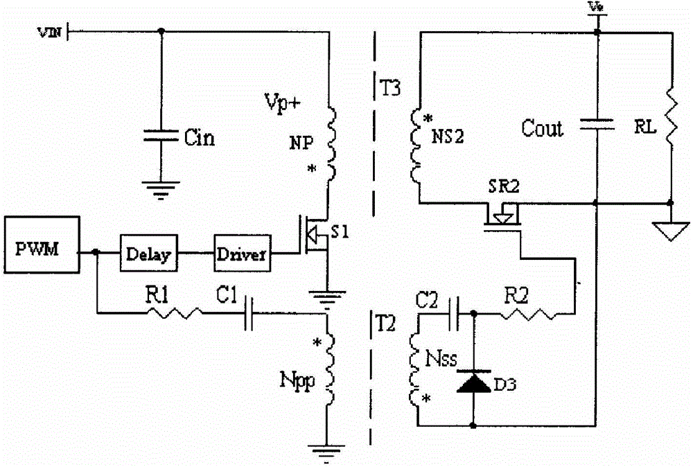
[0043] Figure 5 A schematic diagram of a synchronous rectification driving circuit according to Embodiment 1 of the present invention is shown, including a flyback power conversion primary side circuit 1 , an isolation capacitor driving circuit 2 , and a power conversion secondary side circuit 3 .

[0044] The flyback power conversion primary circuit 1 includes an input capacitor C3, a primary winding Np of a transformer, and a switch MOS transistor S1. One end of the input capacitor C3 is connected to the input positive Vin+, and the other end is connected to the input negative Vin-. One end of the side winding Np is connected to the input positive Vin+, the other end of the transformer primary winding is connected to the drain of the switching MOS transistor S1, and the source of the switching MOS transistor S1 is connected to the input negative Vin-;

[0045] The power conversion secondary circuit 3 includes a secondary winding Ns of a transformer, a synchronous rectificat...

Embodiment 2

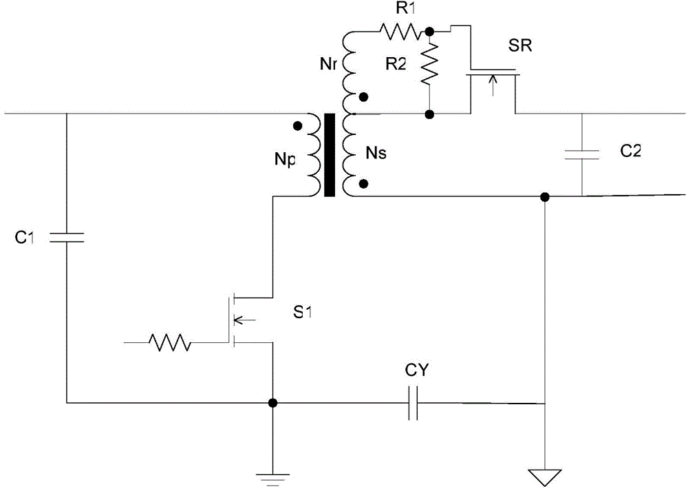
[0053] Image 6 It is the schematic diagram of the synchronous rectification drive circuit of the second embodiment of the present invention. The difference from the first embodiment is that a resistor R1 and a release transistor Q1 are added to the isolation capacitor drive circuit 2, and the resistor R1 is connected in series with the isolation capacitor C1 and the synchronous rectification MOS transistor. Between the gates, the release transistor Q1 is a PNP transistor, the base of the transistor Q1 is connected to one end of the damping resistor R1, the emitter is connected to the other end of the damping resistor R1, and the collector is connected to the negative output terminal VO-.

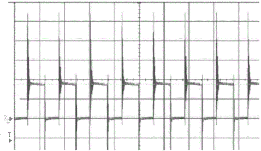
[0054] Its working principle is that the drain-source voltage Vds pulse voltage formed on the switching MOS transistor S1 of the power conversion primary side circuit is a non-ideal pulse voltage.

[0055] The VDS pulse voltage of the primary side circuit of the power converter has a high-f...


PUM


Abstract

The invention discloses a synchronous rectification drive circuit and a synchronous rectification method of a switching power supply, and particularly relates to the synchronous rectification drive circuit and the synchronous rectification method with fly-back topology. Voltage Vds between the drain electrode and the source electrode of a switch tube of the fly-back topology switching power supply is transmitted to the secondary side of the switching power supply through an isolated drive capacitor, the voltage is distributed through the isolated drive capacitor, a grid electrode-source electrode G-S junction capacitor of a synchronous rectification MOS and a common mode capacitor Y, and voltage Vgs which is obtained after voltage distribution is provided for the synchronous rectification MOS for drive. The synchronous rectification drive circuit applied to the switching power supply has the advantages that the circuit is simple, cost is low, the size is small, drive pulse signals have no negative voltage, and the input voltage range of the synchronous rectification drive circuit suitable for the switching power supply is wide.

Description

technical field [0001] The invention relates to a synchronous rectification driving circuit and a synchronous rectification method of a switching power supply, and is particularly suitable for the application field of a switching power supply with a wide input voltage range, small power supply volume and low no-load power consumption. Background technique [0002] With the rapid development of semiconductor devices and VLSI, the demand for high-current, low-voltage, and low-cost isolated switching power supplies has also increased significantly. The Schottky diode with a forward voltage drop of only 0.3V-0.7V rectifies, and the large conduction loss becomes the bottleneck of the miniaturization of the switching power supply. In order to improve the efficiency of low-voltage, high-current switching power supplies, synchronous rectification technology is used for output rectification. In the prior art, two driving methods are generally used, the transformer winding self-driven...

Claims


Application Information

Patent Timeline
Patent Type & Authority Applications(China)
IPC IPC(8): H02M7/155
Inventor 李绍兵
Owner MORNSUN GUANGZHOU SCI & TECH
Why Eureka
Try Eureka