Precise positioning table capable of switching stations

A positioning table and station technology, which is applied in the direction of photolithography exposure equipment, microlithography exposure equipment, etc., can solve the problems of large vertical space, complex structure, and multiple vertical layers of mask tables, and achieve vertical layers Less, simple structure, saving vertical space effect

Active Publication Date: 2015-04-29
SHANGHAI MICRO ELECTRONICS EQUIP (GRP) CO LTD
View PDF6 Cites 10 Cited by
  • Summary
  • Abstract
  • Description
  • Claims
  • Application Information

AI Technical Summary

Problems solved by technology

[0005] First, the switching mechanism in the prior art uses a linear guide rail for guidance, and the error of the guide rail itself and the vertical adjustment error directly affect the Z-direction height change of the loaded object when the graphics are switched, resulting in the Z-direction height change of the loaded object before and after the graphics switch Big
[0006] Second, there may be vertical coupling between the two linear guide rails and the carrying platform in the prior art, which makes it difficult to assemble the two guide rails
[0007] Third, the existing technical mask table has many vertical layers, complex structure, and requires a large vertical space
[0008] In addition, in the existing technology, in order to make the Z-direction height change of the bearing object before and after the graphics switch meet the precision requirements, the installation and adjustment of the mask table often puts forward higher requirements, which increases the difficulty of installation and adjustment.

Method used


Image

  • Precise positioning table capable of switching stations
  • Precise positioning table capable of switching stations
  • Precise positioning table capable of switching stations

Examples


Embodiment 1

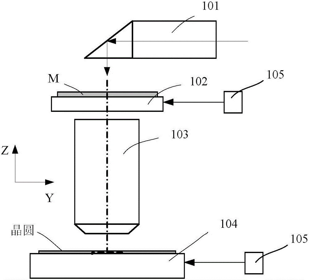
[0039] Please refer to figure 2, the lithography machine mainly includes an illumination system 101 , a mask table 102 , a projection objective lens 103 , a workpiece table 104 , and a laser interferometer 105 . The illumination system 101 provides the exposure light source for the exposure device, the mask table 102 supports and positions the carrying object (M), and the projection objective lens provides the exposure field of view to expose the pattern on the carrying object (M) on the silicon wafer. The workpiece table 104 carries silicon wafers and provides support and positioning functions for silicon wafers / glass substrates. Laser interferometer 105 provides position signals for precise motion control of workpiece stage 104 and mask stage 102 . The carrying object 205 may be a reticle, a silicon wafer or a wafer substrate.

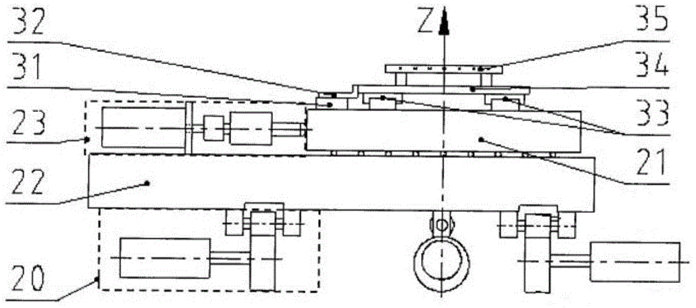
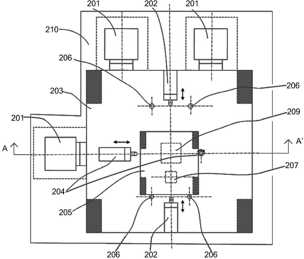
[0040] Please refer to image 3 , and combined with Figure 4 and Figure 5 , this embodiment provides a precision positioning mask table capa...

Embodiment 2

[0054] Please refer to Figure 7 , the difference between this embodiment and Embodiment 1 is that the air bearing 302 includes several air bearing areas, and each of the air bearing areas includes a positive pressure area ring 701 and a vacuum area ring 702, each of the The positive pressure zone ring 701 in the air flotation zone is set outside the vacuum zone ring 702 .

[0055] To sum up, the present invention directly utilizes two clamping mechanisms 202 to push the carrying object, and then realizes the movement of the carrying object. Compared with the movement of the carrying object driven by the movement of the carrying platform in the prior art, the structure is simpler. The vertical space is saved, and at the same time, the present invention realizes the functions of positioning and guiding by using several limit pins and switching guide devices, and can ensure that the movement of the loaded object is carried out between required stations. A mask table with less v...


PUM


Abstract

The invention provides a precise positioning table capable of switching stations. The precise positioning table comprises a station switching device, wherein the station switching device comprises a bearing table, a movable clamping and positioning device and a fixed auxiliary clamping and positioning device and is used for precisely positioning a borne object during station switching. According to the precise positioning table capable of switching the stations, the borne object is driven by virtue of the movable clamping and positioning device and the fixed auxiliary clamping and positioning device and is then moved. Compared with a manner that the movement of the borne object is driven by the movement of the bearing table in the prior art, the structure is relatively simple, and the space in the vertical direction is reduced; meanwhile, the positioning and guiding functions are simultaneously realized, and the movement of the borne object is carried out among the required stations. A mask table which has few vertical levels and a relatively simple structure and does not require much vertical space is provided.

Description

technical field [0001] The invention relates to the field of semiconductor manufacturing, in particular to a mask or a workpiece table and a station switching mechanism thereof. Background technique [0002] The photolithography apparatus in the prior art is mainly used in the field of integrated circuit IC or flat panel display and the manufacture of other micro devices. With a photolithographic apparatus, multilayer masks with different mask patterns are sequentially imaged in precise alignment on a photoresist-coated wafer, such as a semiconductor wafer or an LCD panel. Lithography devices are generally divided into two categories, one is a stepping lithography device, the mask pattern is exposed and imaged on one exposure area of ​​the wafer, and then the wafer moves relative to the mask to move the next exposure area to the mask pattern and under the projection objective, the mask pattern is again exposed on another exposed area of ​​the wafer, and the process is repea...

Claims


Application Information

Patent Timeline
Patent Type & Authority Applications(China)
IPC IPC(8): G03F7/20
Inventor 梁晓叶江旭初魏龙飞王鑫鑫
Owner SHANGHAI MICRO ELECTRONICS EQUIP (GRP) CO LTD
Why Eureka
Try Eureka