Planar low pass band pass triplexer

A triplexer and bandpass filter technology, applied in the field of planar low-pass bandpass triplexer, can solve the problem of independent design of low-pass bandpass filter, inability to apply low-pass-bandpass triplexer, The performance of the low-pass filter needs to be improved to achieve the effect of light weight, reduced design difficulty, and simple structure

Inactive Publication Date: 2017-06-06
SOUTH CHINA UNIV OF TECH
View PDF6 Cites 0 Cited by
  • Summary
  • Abstract
  • Description
  • Claims
  • Application Information

AI Technical Summary

Problems solved by technology

[0004] In 1999, M.H.Capstisk published a paper entitled "Microstriplowpass-bandpass diplexer topology" on "IEEE Electronic Letter", the structure is as follows figure 1 As shown, it simply connects a low-pass filter and a band-pass filter to form a low-pass-band-pass duplexer. This article is not detailed, and it is difficult to independently design the low-pass and band-pass filters
[0005] In 2013, Pu-Hua Deng et al published a paper entitled "Design of Microstrip Lowpass-Bandpass Diplexer" on "IEEE MICROWAVE AND WIRELESS COMPONENTSLETTERS", the structure is as follows figure 2 As shown, the low-pass filter and the band-pass filter are connected through a quarter-wavelength converter to form a low-pass-band-pass duplexer. Although the low-pass and band-pass filters can be designed independently, this structure cannot Applied to low-pass-band-pass triplexer design, and its low-pass filter performance needs to be improved

Method used


Image

  • Planar low pass band pass triplexer
  • Planar low pass band pass triplexer
  • Planar low pass band pass triplexer

Examples


Embodiment

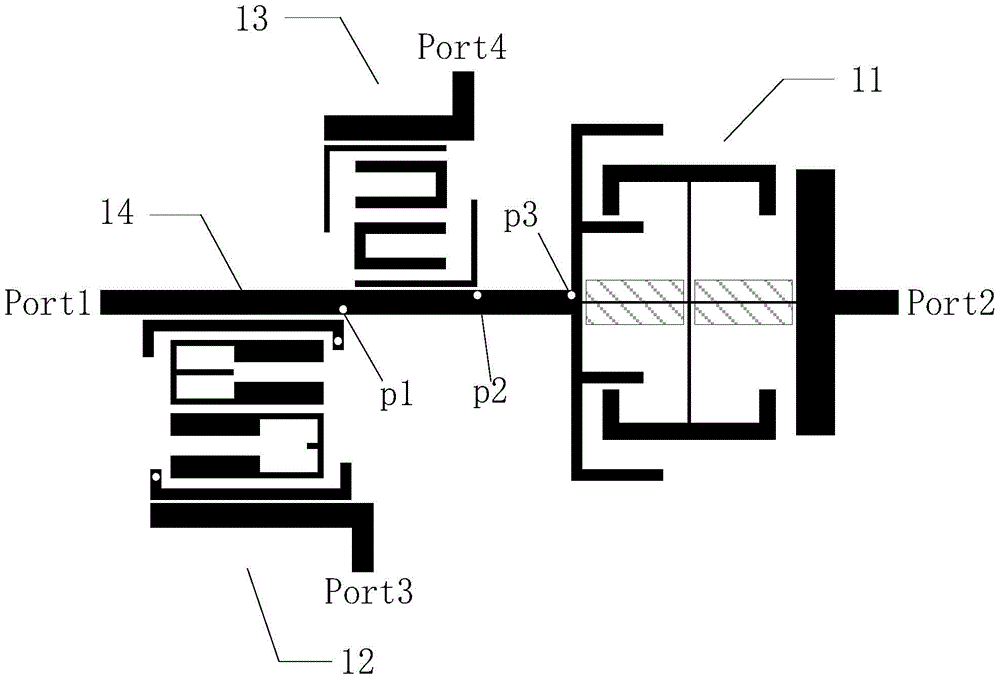
[0044] See image 3 , image 3 It is a schematic diagram of the overall structure of the planar low-pass band-pass triplexer disclosed in the embodiment of the present invention. The planar low-pass band-pass triplexer as shown in the figure is fabricated on a dielectric substrate in the form of a printed circuit board. On the same surface of the dielectric substrate, an input end feeder port1 for inputting electromagnetic wave signals, a low The pass filter 11 and the low pass filter 11 are used to output the output terminal feeder port2 of the electromagnetic wave signal, a first band pass filter 12 working in the frequency band 1 and the first band pass filter 12 is used to output the electromagnetic wave signal The output end feeder head port3, a second bandpass filter 13 working in the frequency band 2 and the second bandpass filter 13 are used to output the output end feeder head port4 of the electromagnetic wave signal, a 50 ohm first transmission line 14, The other s...


PUM


Abstract

The invention discloses a planar lowpass-bandpass triplexer. The planar lowpass-bandpass triplexer comprises a lowpass filter (11), a bandpass filter (12), a bandpass filter (13) and a transmission line (14), wherein two branch node loaded resonators in the lowpass filter (11) generate two transmission zeros, the frequency of one transmission zero is identical with the center frequency of the bandpass filter (12), the frequency of the other transmission zero is identical with the center frequency of the bandpass filter (13), and accordingly center frequency signals of the two bandpass filters are under the short-circuit condition when the branch node loaded resonators are located at the input end of the lowpass filter (11); the transmission line (14) is provided with a locating point p1, a locating point p2 and a locating point p3, the distance between the p1 and the p3 corresponds to quarter wavelength of the center frequency of one bandpass filter, and the distance between the p2 and the p3 corresponds to quarter wavelength of the center frequency of the other bandpass filter; according to quarter wavelength impedance inversion, the center frequency signal of the bandpass filter (12) is under the open-circuit condition when the bandpass filter (12) is located at the p1, and the center frequency signal of the bandpass filter (13) is under the open-circuit condition when the bandpass filter (13) is located at the p2. The lowpass-bandpass filters of the triplexer are designed conveniently and independently and enabled not to influence each other, design cycles can be shortened, and design efficiency can be improved.

Description

technical field [0001] The invention relates to the technical field of planar filters, in particular to a planar low-pass band-pass triplexer. Background technique [0002] In recent years, with the rapid development of wireless communication technology, people's demand for wireless communication services is increasing day by day. In order to meet people's various needs, the communication system must be compatible with multiple communication standards when designing. Today's wireless communication systems are basically multiplexing systems. For time division multiplexing, the problem can be solved as long as the receiving and transmitting are arranged in different time slices. For frequency division multiplexing, in order to reduce the number of filter devices, the It is necessary to design a special device to isolate different signals without causing interference with each other. Such a device is a multiplexer. [0003] At present, the design of multiplexers composed of ba...

Claims


Application Information

Patent Timeline
Patent Type & Authority Patents(China)
IPC IPC(8): H01P1/20H01P1/203
Inventor 陈付昌胡豪涛邱捷铭褚庆昕
Owner SOUTH CHINA UNIV OF TECH
Why Eureka
Try Eureka