
Cascade bilateral soft switch DC/DC circuit topology

A soft switch and circuit technology, applied in the direction of electrical components, electric variable adjustment, control/regulation system, etc., can solve problems such as poor electromagnetic performance and high stress of switching tubes, and achieve simple and reliable control, reduced voltage stress, and complexity Reduced effect

Inactive Publication Date: 2015-04-29
NANCHANG UNIV
View PDF4 Cites 5 Cited by
  • Summary
  • Abstract
  • Description
  • Claims
  • Application Information

AI Technical Summary

Problems solved by technology

[0002] At present, the circuit topologies of bidirectional DC / DC converters are generally divided into two categories: one is non-isolated, and its main features are simple structure, small size, light weight, low power and high efficiency, but it is only suitable for low power without electrical Isolation occasions; the other type is the isolation type. The introduction of a transformer not only solves the electrical isolation between the low-voltage side and the high-voltage side, but also greatly increases the power of the converter. Serious, poor electromagnetic performance and other problems are difficult to solve

Method used


Image

  • Cascade bilateral soft switch DC/DC circuit topology
  • Cascade bilateral soft switch DC/DC circuit topology
  • Cascade bilateral soft switch DC/DC circuit topology

Examples


Embodiment Construction

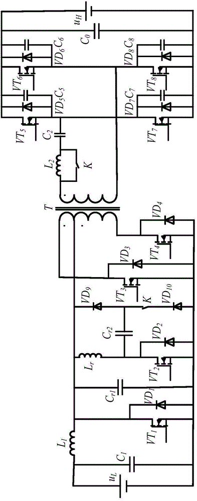
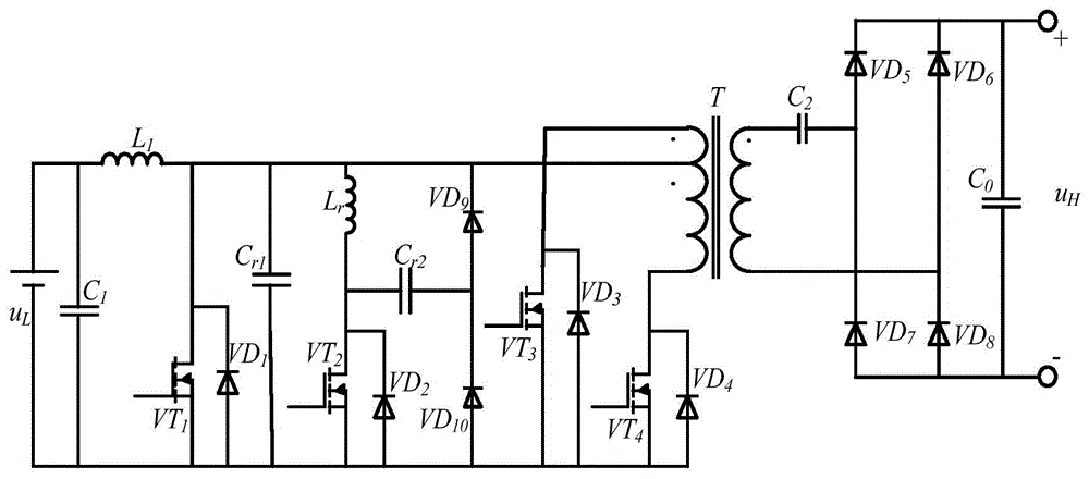
[0024] For the topology of the cascaded bidirectional soft switch DC / DC circuit described in the present invention, please refer to the attached figure 1 , it is divided into the forward working state during boost conversion and the reverse working state during buck conversion in practical applications. H It must be converted into a load form, that is, the impedance of the motor; when step-down, the low-voltage side DC power supply u L It must be converted into the load form, that is, the impedance of the battery. For ease of understanding, the load form is treated as no-load.

[0025] The specific implementation of the present invention will be described in detail below in conjunction with the accompanying drawings and working principles.

[0026] The specific boost conversion principle is as follows.

[0027]When the car is starting, accelerating or climbing, the controller closes the high-voltage side VT 5 ~VT 8 The driving signal, the relay K is closed, so that the sa...


PUM


Abstract

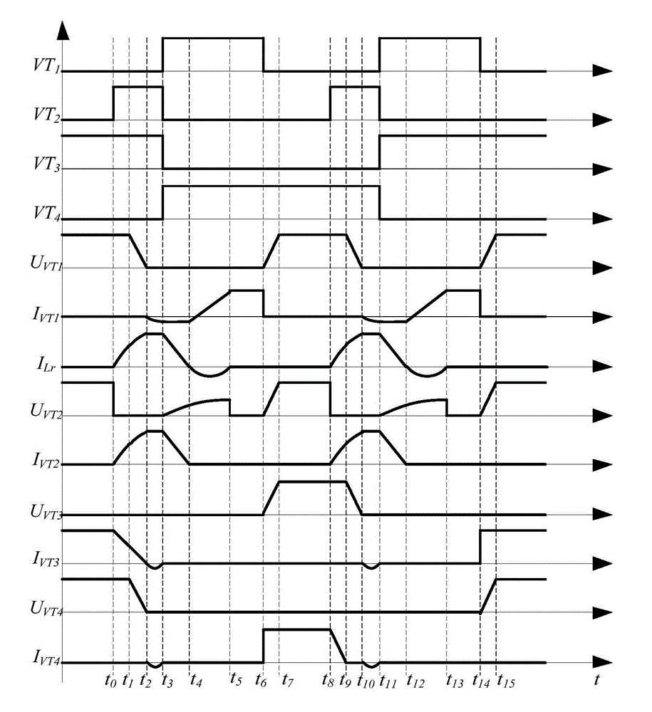
The invention discloses a cascade bilateral soft switch DC / DC circuit topology. The cascade bilateral soft switch DC / DC circuit topology comprises a preceding stage boosted circuit, an auxiliary circuit, a post-stage push pull transformer and a full-bridge circuit, which are connected in series in sequence, wherein the auxiliary circuit comprises a resonant inductor Lr, a resonant capacitor Cr2, an auxiliary switch VT2 containing an anti-parallel body diode VD2, fast recovery diodes VD9 and VD10, and a relay K; one end of the resonant inductor Lr is connected with the negative electrode of the fast recovery diode VD9; the other end of the resonant inductor Lr is respectively connected with the positive electrode of the fast recovery diode VD10 and the drain electrode of the auxiliary switch VT2; the source electrode of the auxiliary switch VT2 is connected with the anode of the fast recovery diode VD10; the negative electrode of the fast recovery diode VD10 is connected with one end of the relay K; the other end of the relay K is respectively connected with the negative electrode of the resonant capacitor Cr2 and the anode of the fast recovery diode VD9. The cascade bilateral soft switch DC / DC circuit topology is simple and reliable in control, simple in circuit structures, easy to realize, low in device cost, low in switch loss, low in voltage stress of the switch, high in conversion efficiency and low in circuit conduction loss.

Description

technical field [0001] The invention belongs to the technical field of electric vehicles, in particular to the electric vehicle circuit topology. technical background [0002] At present, the circuit topologies of bidirectional DC / DC converters are generally divided into two categories: one is non-isolated, and its main features are simple structure, small size, light weight, low power and high efficiency, but it is only suitable for low power without electrical Isolation occasions; the other type is the isolation type. The introduction of a transformer not only solves the electrical isolation between the low-voltage side and the high-voltage side, but also greatly increases the power of the converter. Serious, poor electromagnetic performance and other problems are difficult to solve. Contents of the invention [0003] The object of the present invention is to provide a cascaded bidirectional soft switching DC / DC circuit topology suitable for electric vehicles, which is ...

Claims


Application Information

Patent Timeline
Patent Type & Authority Applications(China)
IPC IPC(8): H02M3/337
CPCH02M3/337H02M1/0048H02M1/0058Y02B70/10
Inventor 万晓凤谌新余运俊胡伟康利平郑博嘉
Owner NANCHANG UNIV
Learn More