
Reset circuit with high response speed and low temperature coefficient

A technology with low temperature coefficient and response speed, which is applied in the reset circuit with low temperature coefficient and high response speed, and can solve problems such as slow response speed after power-off, failure to meet circuit system requirements, instability, etc.

Active Publication Date: 2015-04-29
BEIJING TONGFANG MICROELECTRONICS
View PDF4 Cites 14 Cited by
  • Summary
  • Abstract
  • Description
  • Claims
  • Application Information

AI Technical Summary

Problems solved by technology

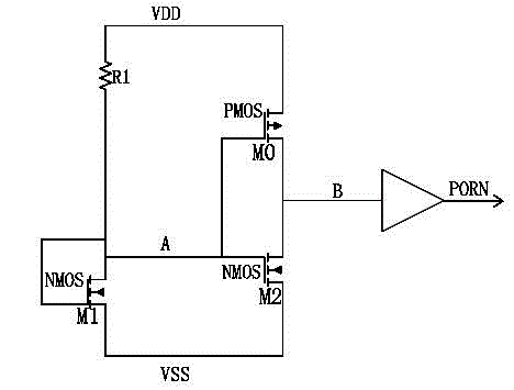
[0013] obviously, , are temperature dependent, and exhibits a larger negative temperature coefficient (compared to into a square relationship), which eventually leads to the output reset signal of the voltage detection circuit having a large temperature coefficient, which cannot meet the requirements of the current circuit system for the reset signal
[0014] The power-off response speed of the above-mentioned traditional circuit is very low. When the power supply voltage is normal, PORN is at high level, figure 1 The middle point B is also high level, the M2 transistor is in the saturation region and the M0 and M2 transistor channels continue to flow
When the power supply loses power quickly, the VDD voltage drops, and the potential of the node at point A will fluctuate greatly due to the influence of the parasitic capacitance of the M0 transistor. The M0 and M2 transistors There are also large voltage fluctuations
M0 transistor's decreases and eventually causes the M0 transistor to turn off, the M2 transistor due to Unstable drop causes B node to not change to low level quickly
[0015] To sum up, the temperature of the reset circuit in the prior art has a great influence on it, and the power-off response speed is slow, which cannot well meet the requirements of current integrated circuits for reset signals with high response speed and low temperature coefficient.

Method used


Image

  • Reset circuit with high response speed and low temperature coefficient
  • Reset circuit with high response speed and low temperature coefficient
  • Reset circuit with high response speed and low temperature coefficient

Examples


Embodiment Construction

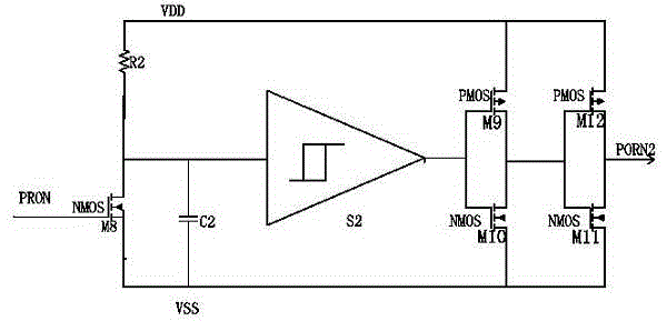
[0030] see figure 2 The reset circuit of the present invention includes a voltage sampling circuit 101 , a voltage detection circuit 102 and an output circuit 103 connected in sequence. The voltage sampling circuit 101 includes a first resistor R1 using a current source, a passive resistor or an active device PMOS transistor, one end of the first resistor R1 is connected to the power supply VDD, and the other end of the first resistor R1 is connected to the drain of the first NMOS transistor M1 and gate. The source of the first NMOS transistor M1 is connected to the drain of the second NMOS transistor M2. The gate of the second NMOS transistor M2 is connected to the drain of the first NMOS transistor M1, and the source of the second NMOS transistor M2 is grounded to VSS. The gate of the first NMOS transistor M1 and the gate of the second NMOS transistor M2 are connected to the drain of the first NMOS transistor M1. The first NMOS transistor M1 is a native NMOS transisto...


PUM


Abstract

The invention discloses a reset circuit with a high response speed and a low temperature coefficient, and relates to the technical field of integrated circuits. The reset circuit includes a voltage sampling circuit, a voltage detection circuit and an output circuit, one connected with another in sequence, wherein the voltage sampling circuit includes a first resistor, a first NMOS transistor and a second NMOS transistor; the voltage detection circuit includes a first CMOS inverter and a first capacitor; the first CMOS inverter includes a first PMOS transistor and a third NMOS transistor; the output circuit includes a first Schmitt trigger, a second CMOS inverter and a third CMOS inverter, one connected with another in sequence; the output end of the output circuit is connected to the input end of a time-delay circuit; the time-delay circuit adjusts the time for outputting reset signals and shapes the reset signals according to reset requirements of the circuit system. The reset circuit provided by the invention is high in response speed with a near-zero temperature coefficient, and can fully ensure the reliability of the operations.

Description

technical field [0001] The invention relates to the technical field of integrated circuits, in particular to a reset circuit with high response speed and low temperature coefficient that can be integrated into a chip. Background technique [0002] With the rapid development of large-scale integrated circuits, the reset circuit can be said to be a circuit module in every IC chip circuit. It is mostly used in digital systems as asynchronous reset signals, to detect whether the power supply voltage is normally powered on and off, and to ensure that the circuit internal The correctness of digital logic. [0003] The reset voltage requires that the correct reset signal can be given under various power-on and power-off conditions, so the voltage detection circuit contained in this circuit cannot use the conventional sampling circuit to sample the power supply voltage, and use the analog comparator to sample The method of comparing the voltage with the reference voltage output by...

Claims


Application Information

Patent Timeline
IPC IPC(8): H03K17/22H03K17/28
Inventor 霍俊杰邰晓鹏孙志亮李侠侯艳岳超黄钧陈震
Owner BEIJING TONGFANG MICROELECTRONICS
Learn More