Multi-point correction method and system for infrared focal plane

An infrared focal plane and multi-point correction technology, which is applied in the field of infrared focal plane multi-point correction methods and systems, can solve problems such as inconsistency in response output of detection units

Active Publication Date: 2015-04-29
IRAY TECH CO LTD
View PDF2 Cites 19 Cited by
  • Summary
  • Abstract
  • Description
  • Claims
  • Application Information

AI Technical Summary

Problems solved by technology

[0005] The purpose of the present invention is to provide a multi-point correction method for infrared focal plane, aiming to solve the inherent non-uniformity of...

Method used


Image

  • Multi-point correction method and system for infrared focal plane
  • Multi-point correction method and system for infrared focal plane
  • Multi-point correction method and system for infrared focal plane

Examples


Embodiment Construction

[0047] In order to make the object, technical solution and advantages of the present invention clearer, the present invention will be further described in detail below in conjunction with the accompanying drawings and embodiments. It should be understood that the specific embodiments described here are only used to explain the present invention, not to limit the present invention.

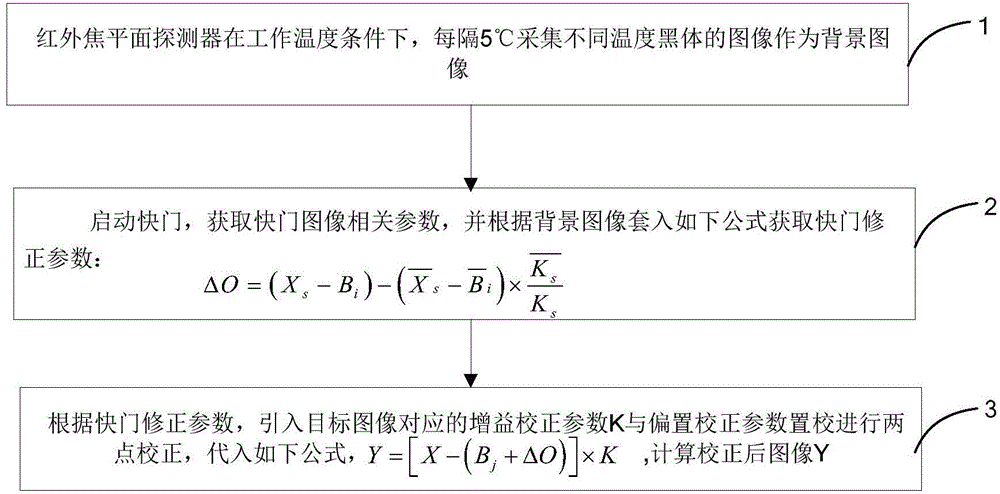
[0048] figure 1 It is a flow chart of a multi-point correction method for an infrared focal plane provided by the present invention, and is described in detail as follows:

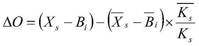
[0049] Step 1, within the working temperature range of the infrared focal plane detector, images of black bodies at different temperatures are collected every 5°C as background images;

[0050] In this example, an array of photosensitive elements is arranged on the infrared focal plane, and infrared rays emitted from a wireless distance are imaged on these photosensitive elements on the focal plane of the system through an opt...


PUM


Abstract

The invention belongs to the technical field of image processing, and particularly relates to a multi-point correction method for an infrared focal plane. The method comprises steps as follows: step 1, an infrared focal plane detector acquires images of different temperature black bodies at the working temperature in every other 5 DEG C and uses the images as background images; step 2, a shutter is started, a related parameter of a shutter image is acquired, and a shutter correction parameter is acquired with the following formula shown in the specification according to the background images, wherein delta O is the shutter correction parameter, the related parameter of the shutter image comprises the mean value Xs of a shutter image Xs and the shutter image, Bi is the i background image, Bi is the mean value of the background images, Ks is a gain correction parameter corresponding to the shutter image, and Ks is the mean value of the Ks; step 3, according to the shutter correction parameter delta O, a gain correction parameter K and a bias correction parameter Bj which correspond to an object image are introduced into the following formula shown in the specification for two-point correction, and a corrected image Y is calculated, wherein X is the to-be-corrected image, Y is the corrected image, delta O is the shutter correction parameter, Bj is the j background image, and K is the gain correction image.

Description

technical field [0001] The invention belongs to the technical field of image processing, and in particular relates to a method and system for multi-point correction of an infrared focal plane. Background technique [0002] Infrared focal plane array imaging system has become the development trend of infrared thermal imaging technology due to its advantages of high sensitivity, small size, compact structure, long range, good anti-interference, strong ability to penetrate smoke and haze, and can work around the clock. The staring infrared focal plane array has become the mainstream detection device for the development of future infrared thermal imaging systems. [0003] Based on these excellent characteristics of the infrared imaging system, it has been widely used in various military (such as early warning, detection and tracking, imaging guidance, etc.) and civil (such as scientific research, remote sensing, industrial monitoring, medical, etc.) fields. An infrared detector...

Claims


Application Information

Patent Timeline
IPC IPC(8): H04N5/232H04N5/33
Inventor 马兆峰黄星明李晶
Owner IRAY TECH CO LTD
Why Eureka
Try Eureka