A microfluidic device with high-frequency vibration processing

A high-frequency vibration and micro-flow technology, applied in the field of micro-flow, can solve problems such as inapplicability of digital micro-flow devices, and achieve the effects of accelerating sample mixing, realizing cracking, and reducing surface adhesion

Active Publication Date: 2015-05-06
吴传勇 +1
View PDF2 Cites 5 Cited by
  • Summary
  • Abstract
  • Description
  • Claims
  • Application Information

AI Technical Summary

Problems solved by technology

Moreover, it is difficult to use a homogenizer to break up cells on digital microfluidic devices, because the cell bomb method requires high pressure (~25000psi), so it is not suitable for digital microfluidic devices

Method used


Image

  • A microfluidic device with high-frequency vibration processing
  • A microfluidic device with high-frequency vibration processing
  • A microfluidic device with high-frequency vibration processing

Examples


Embodiment Construction

[0037] The implementation of the present invention will be illustrated by specific specific implementation examples below, and those skilled in the art can easily understand other advantages and effects of the present invention from the content disclosed in this specification.

[0038] see Figure 1 to Figure 6 . It should be noted that the structures, proportions, sizes, etc. shown in the drawings attached to this specification are only used to match the content disclosed in the specification, for those who are familiar with this technology to understand and read, and are not used to limit the implementation of the present invention. Limiting conditions, so there is no technical substantive meaning, any modification of structure, change of proportional relationship or adjustment of size, without affecting the effect and purpose of the present invention, should still fall within the scope of the present invention. The disclosed technical content must be within the scope cover...


PUM


Abstract

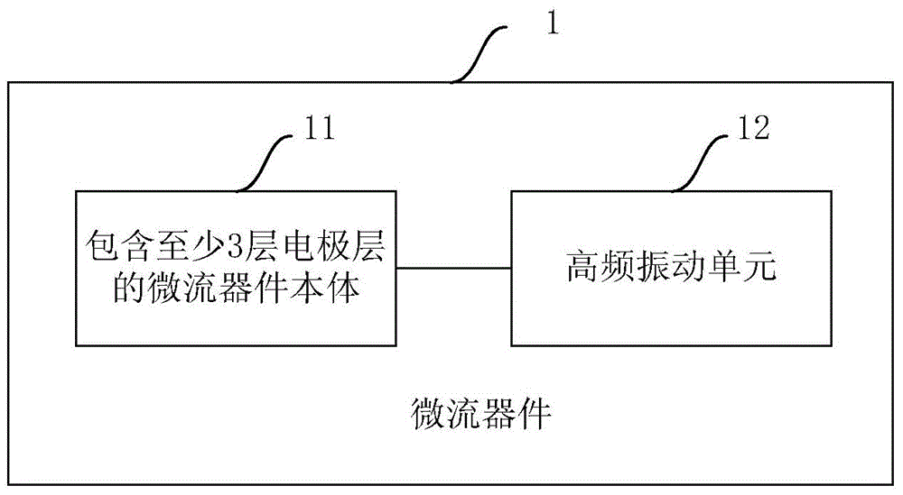
A microfluidic device with high-frequency vibration processing is provided. The microfluidic device at least comprises a microfluidic device main body, and a high-frequency vibration unit disposed at a position corresponding to the microfluidic device main body, wherein the microfluidic device main body comprises at least three electrode layers, a plurality of the electrode layers are on a first substrate, and the one left of the electrode layers is on a second substrate opposite to the first substrate, the electrode layers are separated by dielectric layers, and the high-frequency vibration unit comprises a signal generator used for generating high-frequency vibration signals and a transducer used for converting the high-frequency vibration signals generated by the signal generator into mechanical energy. The microfluidic device perform treatments for samples, such as treatments of reducing surface adhesion of particles, uniformly dispersing aggregated particles, accelerating sample mixing, cutting DNA into small fragments, achieving cell lysis, and the like.

Description

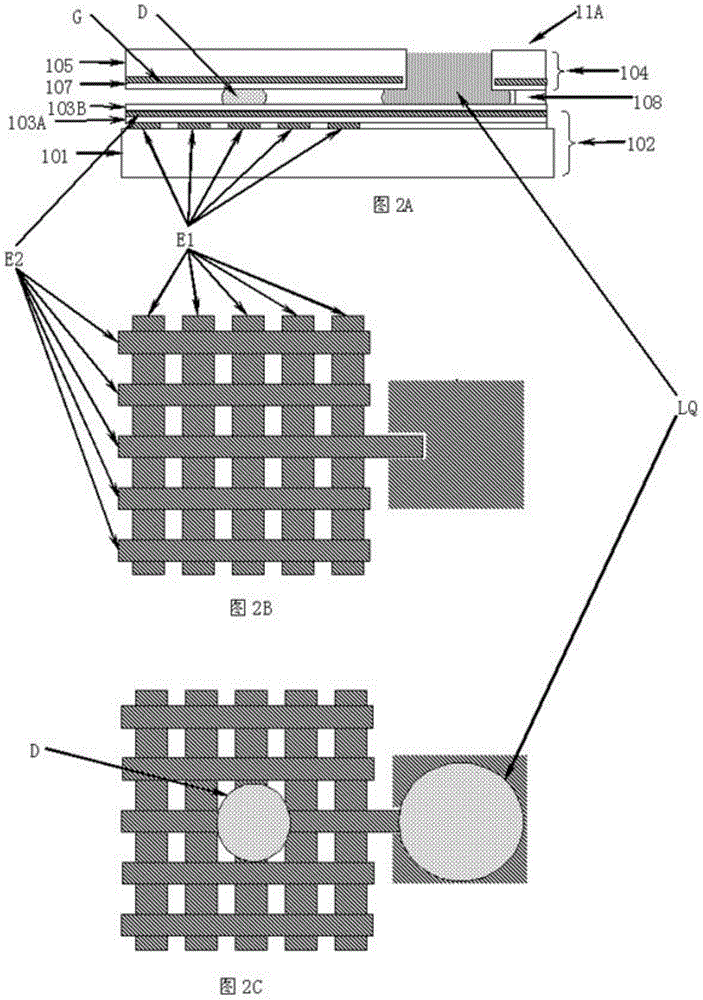
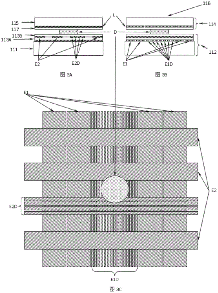
technical field [0001] The invention relates to the field of microfluidics, in particular to a microfluidic device with high-frequency vibration processing. Background technique [0002] In recent years, Digital Microfluidics (or DMF) based on electrowetting has attracted attention in various fields because it can not only manipulate a single droplet, but also has the advantages of miniaturization, integration and automation. By performing electrowetting / electrophoresis / dielectrophoresis operations on the device, digital microfluidic devices reduce the amount of samples / reagents, shorten the detection time, and make sample processing more convenient. However, when using digital microfluidic devices, it is often encountered that particles adhere to the surface of the device to cause surface contamination, and the particles tend to aggregate into clusters and cannot be uniformly dispersed in the solution. In addition, intact cells (or spores or tissue ) cleavage and extractio...

Claims


Application Information

Patent Timeline
Patent Type & Authority Applications(China)
IPC IPC(8): B01L3/00
Inventor 吴传勇汪志芳彭显然
Owner 吴传勇
Why Eureka
Try Eureka