
Pyrolysis-gasification integrated treatment device and method

A processing device and pyrolysis technology, which is applied in the gasification process, the manufacture of combustible gas, and the gasification of granular/powdered fuels, etc., and can solve the problems of complex tar components, slag blocking, and difficulty in refining.

Active Publication Date: 2020-03-27
WANHUA CHEM GRP CO LTD +1
View PDF9 Cites 2 Cited by
  • Summary
  • Abstract
  • Description
  • Claims
  • Application Information

AI Technical Summary

Problems solved by technology

Some scholars have studied coal gasification-pyrolysis integrated technology, using gasification preheating to carry out pyrolysis reaction, improving heat utilization rate, and recovering tar products in the pyrolysis process; however, the components in tar are very complex and difficult to extract, requiring Further hydrocracking to produce light tar; tar cooling, heating and cracking process will inevitably lead to energy waste, therefore, some scholars turn to the catalytic cracking of hot tar
[0004] Patent CN109054901A relates to a descending bed-fluidized bed series gasification method and device. The pyrolysis raw material swirls down along the wall, and the raw material is pyrolyzed by high-temperature synthesis gas and slag heat generated by pulverized coal gasification, but there is The slag accumulates at the bottom of the furnace body to cause the risk of slag blocking, and the pyrolysis semi-coke and slag adhere to the furnace wall, which reduces the carbon conversion rate in the entrained bed gasification process; the patent CN106085507A relates to a The slag gasifier of the slag plant adopts the water quenching method to cool the slag sample. During the heat conversion process, the heat is converted into the increase of the temperature of the quenching water, which reduces the full utilization of heat.

Method used


Image

  • Pyrolysis-gasification integrated treatment device and method
  • Pyrolysis-gasification integrated treatment device and method
  • Pyrolysis-gasification integrated treatment device and method

Examples


Embodiment 1

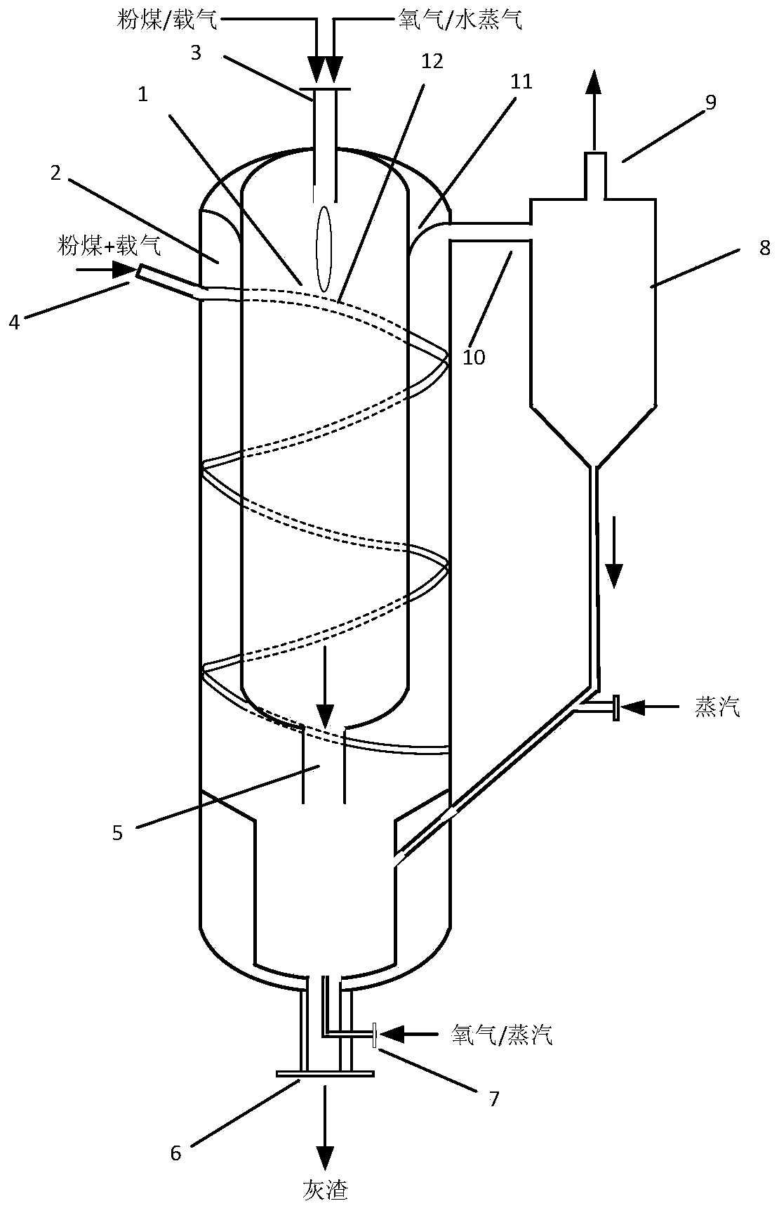
[0063] A pyrolysis-gasification integrated treatment device, such as figure 1 As shown, the device includes a gasification furnace 1 and a pyrolysis furnace 2, the gasification furnace 1 is arranged in the upper area of ​​the pyrolysis furnace 2 furnace cavity, and the two furnace bodies are coaxially distributed; the top of the gasification furnace 1 is provided with Pulverized coal feed port 3, with gasification discharge port 5 at the bottom;

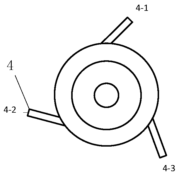
[0064] The upper part of the pyrolysis furnace 2 is provided with three pyrolysis raw material inlets 4 and a synthesis gas outlet 10, and the bottom is provided with a gasification agent inlet 7 and a slagging outlet 6; the three pyrolysis raw material inlets 4 are on the same plane along the pyrolysis The outer wall of the furnace is evenly distributed (such as figure 2 shown).

[0065] The inlet of the cyclone separator 8 is connected with the synthesis gas outlet 10, and the bottom of the cyclone separator 8 is connected with ...

Embodiment 2

[0071] A pyrolysis-gasification integrated treatment method using the device of embodiment 1, the steps comprising:

[0072] 1) It includes two stages of gasification and one stage of pyrolysis, wherein: the gasification furnace cavity of gasification furnace 1 is a gasification zone; The gap is the pyrolysis area; the lower part of the furnace chamber of the pyrolysis furnace 2, which is located below the furnace body of the gasification furnace 1, is the second-stage gasification area;

[0073] 2) First-stage gasification area: pulverized coal (Shenhua coal) and gasification gas enter the furnace cavity of gasifier 1 from the pulverized coal feed port 3 at the top of gasifier 1 through the nozzle, and gasification reaction occurs at 1250-1300°C to generate A section of hydrogen-rich gas and a section of ash are discharged from the first section of gasification area through the gasification outlet 5, a section of hydrogen-rich gas deflects upwards and enters the pyrolysis are...

Embodiment 3

[0112] Only in following difference with embodiment 2:

[0113] In step 2), the ratio of oxygen to pulverized coal (volume / mass) is adjusted to 0.7:1; the mass ratio of water vapor to pulverized coal is 0.18:1; pulverized coal is changed to CO 2 delivery;

[0114] Step 3) The pyrolysis raw material is mixed with Shenhua coal powder and chlorine-free TDI tar solid waste at a ratio of 1:1. The ash melting point of the mixture is about 1200°C. Adjust the carrier gas N 2 / CO 2 The carrier gas ratio is 1:1.

[0115] The volume percentage composition of the hydrogen-rich gas in the first section includes H 2 24% or so, CO 62% or so, CO 2 Around 5%, CH 4 About 0.4%, and other sulfur- and nitrogen-containing gases; the first stage of ash residue carbon is about 9-13wt%, and the temperature of hydrogen-rich gas is about 1100°C.

[0116] After passing through the pyrolysis zone, the hydrogen content increased by about 3%, CH 4 Content increased by about 2%, C 2 ~C 4 Hydrocarb...


PUM


Abstract

The invention relates to a pyrolysis-gasification integrated treatment device and method. A two-section gasification and one-section pyrolysis device combined design is adopted, a first-section gasification area furnace body and a pyrolysis furnace body are coaxially distributed, and the first-section gasification area and the second-section gasification area are distributed up and down. Tar produced by the coal pyrolysis section is completely cracked by the high temperature of hydrogen-rich gas generated by the first-section gasification and second-section gasification, thus adjusting the hydrogen-carbon ratio in the synthesis gas at an outlet, and reducing the environmental protection problem caused by tar in subsequent wastewater; meanwhile, the two-section gasification technology is employed at the same time to further improve the residual carbon in ash residue and enhance the carbon conversion rate of the raw material. On the basis, the pyrolysis part is provided with three strands of feeding materials, a flow guide weir, a flow guide plate and the like to realize complete cracking of pyrolysis tar, the carbon conversion rate is high, the phenomenon of adhesion of pyrolysis semicoke and slag and the risk of slag blockage caused by slag accumulation at the bottom of the furnace body are avoided. The device and method are suitable for low-rank coal upgrading, inferior coal gasification and solid waste cracking resource utilization.

Description

technical field [0001] The invention belongs to the technical field of coal gasification and solid waste treatment and utilization, and relates to a pyrolysis-gasification integrated treatment device and method. Background technique [0002] With the development of my country's coal chemical industry, high-quality coal resources are gradually decreasing, while low-rank coal is easily weathered in the air due to its high water content and strong reactivity, and is difficult to store and transport. Combustion will cause serious air pollution. At present, low-rank coal such as lignite is mainly used for combustion and power generation, and a small amount of coal is used for chemical industry, which causes a lot of waste of resources and wastes transmission power. Effective utilization of low-rank coal plays an important role in reducing environmental pollution. [0003] At present, coal gasification technology is mainly divided into moving bed, fluidized bed and entrained flow...

Claims


Application Information

Patent Timeline
IPC IPC(8): C10J3/48C10J3/84
CPCC10J3/48C10J3/84C10J2300/0959C10J2300/0976
Inventor 郝成浩高学顺王阳胡耀峰张宏科朱宝
Owner WANHUA CHEM GRP CO LTD
Learn More