
Shot blasting machine

A shot blasting machine and projectile technology, which is applied to used abrasive treatment devices, dispersed particle filtration, combined devices, etc., can solve the problems of easily affecting the surface treatment effect of the workpiece, reducing the impact force, and reducing environmental hygiene, etc. Achieve timely and reliable removal of impurities, improve effect and efficiency, and achieve fast and efficient dust removal.

Active Publication Date: 2015-05-13
宝武特冶航研科技有限公司
View PDF7 Cites 7 Cited by
  • Summary
  • Abstract
  • Description
  • Claims
  • Application Information

AI Technical Summary

Problems solved by technology

[0005] This existing shot blasting machine device has the following defects: in the process of repeated recycling, the projectiles will be continuously worn, broken and thinned. To achieve the required surface treatment effect; at the same time, some fine impurities such as oxide skin on the surface of the workpiece will be knocked off during surface treatment, which will be mixed in the projectile, which will also reduce the surface treatment effect
But this method is cumbersome on the one hand, and on the other hand, it belongs to post-processing, which is not timely
[0006] In addition, when the shot blasting machine is working, it will generate a lot of dust when it hits the surface of the workpiece, which will easily affect the surface treatment effect of the workpiece and reduce the environmental sanitation after the dust leaks out.
In some shot blasting machines, a simple filter will be added to remove dust by filtering, but the dust removal efficiency is low and it is inconvenient to clean and replace the filter element frequently

Method used


Image

  • Shot blasting machine
  • Shot blasting machine

Examples


Embodiment Construction

[0033] The present invention will be further described in detail below in combination with specific embodiments.

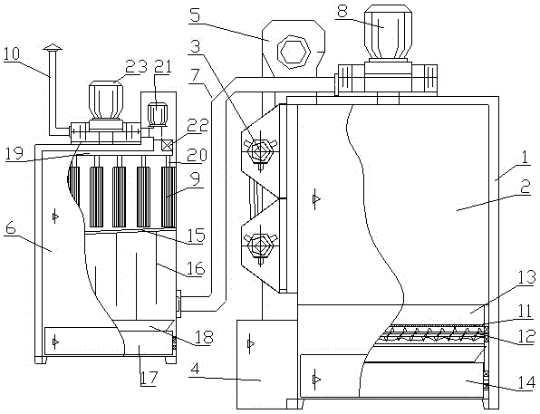
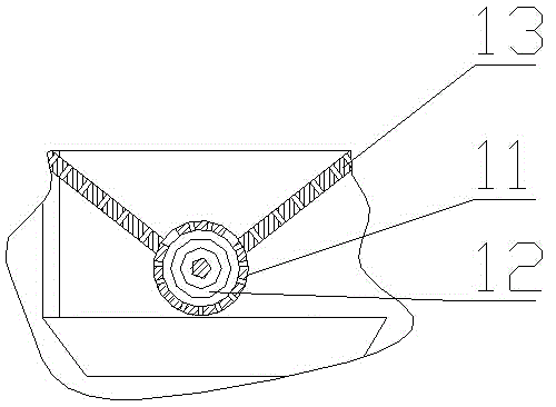
[0034] During specific implementation: if Figure 1-2 As shown, a shot blasting machine includes a frame 1 and a shot blasting machine studio 2 with a box structure arranged on the frame 1, and a shot blasting device 3 is arranged on one side of the shot blasting machine studio 2 facing the room. There is a suspension mechanism for hanging workpieces above the inner cavity of the shot blasting machine working room 2, and a projectile collecting device and a lower sand box 4 are arranged below. The projectile collecting device can collect projectiles dropped in the shot blasting machine working room 2 and send them to In the lower sand box 4, an upper sand box 5 is arranged above the shot blasting machine working room 2, and a lifting device is arranged between the lower sand box 4 and the upper sand box 5 to lift the projectile of the lower sand box 4 into the upp...


PUM


Abstract

The invention discloses a shot blasting machine. The shot blasting machine comprises a rack, a shot blasting machine work room, a shot blasting device, a suspension mechanism, a shot collection device, a lower sand box, an upper sand box, a lifting device and a dust removal device, and is characterized in that a shot sorting structure is arranged in the shot collection device; the dust removal device comprises a dust removal box, the dust removal box is communicated with the top of the upper end of the shot blasting machine work room through a dust absorption pipeline, a dust absorption fan is arranged on the dust absorption pipeline, a plurality of dust removal cloth bags are arranged in the dust removal box, and an upward air outlet pipeline is arranged at the top of the dust removal box and an air flow needs to flow out from the air outlet pipeline through the dust removal cloth bags. The shot blasting machine disclosed by the invention is capable of efficiently and rapidly eliminating dust, realizing sorting during working, and synchronously removing small-diameter shots and impurities, has the advantages of being fast and efficient in dust removal, timely and reliable in impurity removal, capable of avoiding blockage and the like, shot blasting treatment effect and efficiency of the equipment are improved, the service life is prolonged, and the working hygiene of the equipment is improved.

Description

technical field [0001] The invention relates to the field of surface treatment equipment for metal parts, in particular to a shot blasting machine. Background technique [0002] Shot blasting machine is a casting equipment that uses high-speed projectiles ejected from a shot blasting device to clean or strengthen the surface of castings. The shot blasting machine hits the surface of the metal with one or more sand materials to remove some attachments on the metal surface, such as rust, or to obtain a specific surface layer through shot blasting impact. The shot blasting medium can be sand of various specifications, silicon carbide particles, small steel balls, etc. [0003] An existing shot blasting machine has the following structure: a shot blasting machine working room with a box structure, a shot blasting device is arranged on one side of the shot blasting machine working room facing the room, and a useful The suspension mechanism for hanging workpieces is equipped wit...

Claims


Application Information

Patent Timeline
IPC IPC(8): B24C9/00B24C7/00B01D46/02B01D46/04B01D50/00
CPCB01D46/02B01D46/04B01D50/00B24C7/0092B24C9/003B24C9/006
Inventor 吴建军赵伟周红波
Owner 宝武特冶航研科技有限公司
Learn More