
A Micro Downward Pulling Crystal Growth Furnace

A crystal growth furnace, top-down technology, applied in the direction of crystal growth, single crystal growth, self-melt pulling method, etc. Field stabilization, good observation effect, and the effect of reducing interference

Inactive Publication Date: 2017-10-31
HUAZHONG UNIV OF SCI & TECH
View PDF9 Cites 0 Cited by
  • Summary
  • Abstract
  • Description
  • Claims
  • Application Information

AI Technical Summary

Problems solved by technology

[0005] In view of the above defects or improvement needs of the prior art, the object of the present invention is to provide a micro-down pull crystal growth furnace, wherein by improving the structure of its key components and its arrangement, materials and internal structure, it is compatible with Compared with the existing technology, it can effectively solve the problem of uneven temperature field control of the existing micro-downward pull method crystal growth furnace and the inability to accurately adjust the temperature gradient at the crystal growth interface position, and the crystal growth furnace is provided with an observation window, which can Real-time crystal growth can be observed at any time to achieve the technical effect of adjusting crystal growth parameters in time, controlling crystal growth, and improving crystal yield

Method used


Image

  • A Micro Downward Pulling Crystal Growth Furnace
  • A Micro Downward Pulling Crystal Growth Furnace
  • A Micro Downward Pulling Crystal Growth Furnace

Examples


Embodiment 1

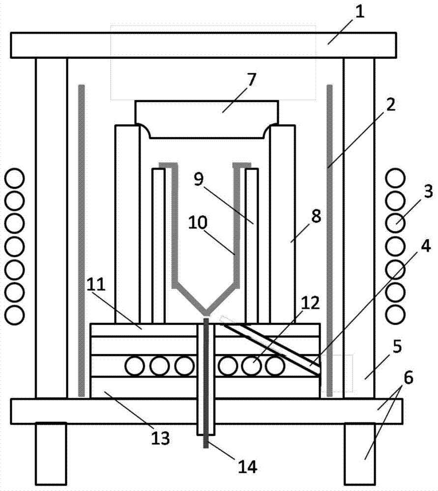
[0033] figure 1 Shown is a schematic diagram of the structure of a slightly downward pulling crystal growth furnace, in which: the outer insulation cover 1 and the outer insulation wall 5 are made of asbestos, the middle insulation cover 7, the middle insulation wall 8, the inner insulation layer 9 and the bottom insulation The layer 13 is formed by pressing and calcining zirconia and alumina with a mass ratio of 1:9, and the bottom insulating support 11 is made of tungsten; the central axis of the observation hole is 45° to the normal line of the top surface of the bottom insulating layer.

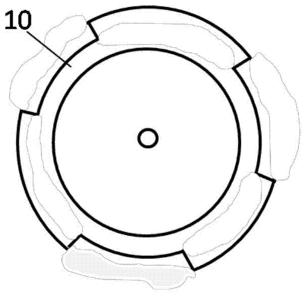
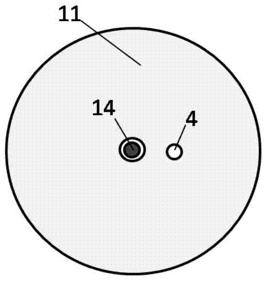
[0034] figure 2 It is a top view schematic diagram of the crucible, and the protruding design of the upper part of the crucible enables the crucible to be conveniently supported on the internal heat insulation layer. image 3 It is a schematic top view of the bottom insulation layer.

[0035] The inner heat insulating layer can be used to support the crucible, which requires that the m...

Embodiment 2

[0040] The configuration of the second embodiment is basically the same as that of the first embodiment, the difference between the two is that the bottom insulation support 11 is made of molybdenum, and the central axis of the observation hole is 60° to the normal line of the top surface of the bottom insulation layer.

[0041] A plurality of water cooling pipelines 12 are set as Figure 4 As shown, 12-A has both cooling water input port and cooling water output port. A port is the cooling water output port, the third 12-A port is the cooling water input port, and so on); Correspondingly, 12-B has both cooling water input port and output port.

Embodiment 3

[0043] The setting of the third embodiment is basically the same as that of the second embodiment, the difference between the two is that the bottom heat insulating support 11 adopts tungsten-molybdenum alloy; and, the outer heat insulating layer (including the outer heat insulating cover 1 and the outer heat insulating wall 5 ) and the middle heat insulating layer are removed (including the middle heat insulating cover 7 and the middle heat insulating wall 8), crystal materials with low melting point can be grown. At this time, the internal heat insulating layer 9 can be evenly arranged to open 3-6 observation holes at a position parallel to the bottom of the crucible, and can be directly observed through the quartz circular tube 2 . The observation window in the bottom insulation layer 13 can be closed to improve the operability of the system.

[0044] An outer shell can also be arranged outside the micro-downward pulling crystal growth furnace to enhance the sealing effect ...


PUM


Abstract

The invention discloses a micro-downward pulling crystal growth furnace, which comprises an upper heat insulation layer and a bottom heat insulation layer (13) arranged from top to bottom, and an observation hole (4) is arranged in the bottom heat insulation layer (13) for observation The hole (4) is tubular, and the included angle between its central axis and the normal to the top surface of the bottom insulation layer (13) is 45° to 60°; the inner layer insulation layer, the middle insulation layer and the bottom insulation layer (13) are all composed of mass Zirconia and alumina with a ratio of 1:9 are pressed and calcined. The observation window provided by the invention can observe the crystal growth condition at the crystal growth interface in time; moreover, the observation window has little influence on the temperature field of the crystal growth furnace, and can further improve the yield of crystal growth.

Description

technical field [0001] The invention belongs to the field of crystal growth, and more specifically relates to a micro-down pull crystal growth furnace. Background technique [0002] The Micro pulling down method, that is, the Micro pulling down method, is a popular preparation technology for small-sized crystals, such as optical fiber single crystals. It is widely used in the research and development of crystal materials. The raw material is melted in a small crucible, and the melt forms a thin layer at the bottom of the crucible under the joint action of gravity and surface tension. The seed crystal is installed on the top of the seed rod, and the cylindrical crystal with a diameter of less than 1mm can be pulled down by contacting with the thin layer through seeding and other techniques. However, due to the extremely thin melt layer, the flow caused by the change of surface tension often plays a leading role in the crystal growth process, and the change of surface tensio...

Claims


Application Information

Patent Timeline
Patent Type & Authority Patents(China)
IPC IPC(8): C30B15/00
Inventor 方海生蒋志敏刘胜王梦莹张舟
Owner HUAZHONG UNIV OF SCI & TECH
Learn More