
Lifting type sound insulation screen based on changes of wind speeds

A sound insulation barrier and lifting technology, which is applied in the direction of sound insulation, noise absorption devices, building components, etc., can solve the problems affecting the normal operation and maintenance of equipment, the analysis process and the scope of treatment are huge, and the automatic adjustment cannot be realized. Practicality and market prospects, fast data access speed, and the effect of less data volume

Active Publication Date: 2015-05-13
杭州绿隆环保科技有限公司
View PDF5 Cites 8 Cited by
  • Summary
  • Abstract
  • Description
  • Claims
  • Application Information

AI Technical Summary

Problems solved by technology

[0004] (1) Sound source treatment process: This method requires all noise sources in the entire plant area to be analyzed one by one and designed for treatment process. Although the noise reduction effect is good, the analysis process and treatment scope are relatively large, and the final investment cost It is often 2-5 times that of the sound barrier process
In addition, due to the relatively compact arrangement of equipment in the factory area, the implementation of many noise reduction measures will seriously affect the normal operation and maintenance of equipment
[0005] (2) Conventional sound barrier technology: Except for the fully enclosed sound barrier, the rest of the sound barriers are limited by the wind resistance load index of the barrier
[0007] In the prior art, there are also sound insulation barriers that can be adjusted in height, such as the Chinese Patent Publication No. CN102733502A, an invention patent application named Movable Lifting Sound Insulation Screen, which discloses a method of disassembling and assembling to realize The technical scheme of adjusting the height of the sound insulation screen, although this scheme can indeed realize the adjustment of the height of the noise insulation screen according to the needs, it has the following defects: (1) The disassembly and assembly of this scheme need to be manually operated, and cannot Realize automatic adjustment; (2) Due to the heavy weight of the sound insulation panel, manual operation on it requires a lot of manpower, and the efficiency is not high; (3) This scheme cannot intelligently adjust the height of the sound insulation panel according to the wind speed, and cannot Meet the strength requirements for sound insulation screens in coastal areas when super typhoons come suddenly

Method used


Image

  • Lifting type sound insulation screen based on changes of wind speeds
  • Lifting type sound insulation screen based on changes of wind speeds
  • Lifting type sound insulation screen based on changes of wind speeds

Examples


Embodiment 1

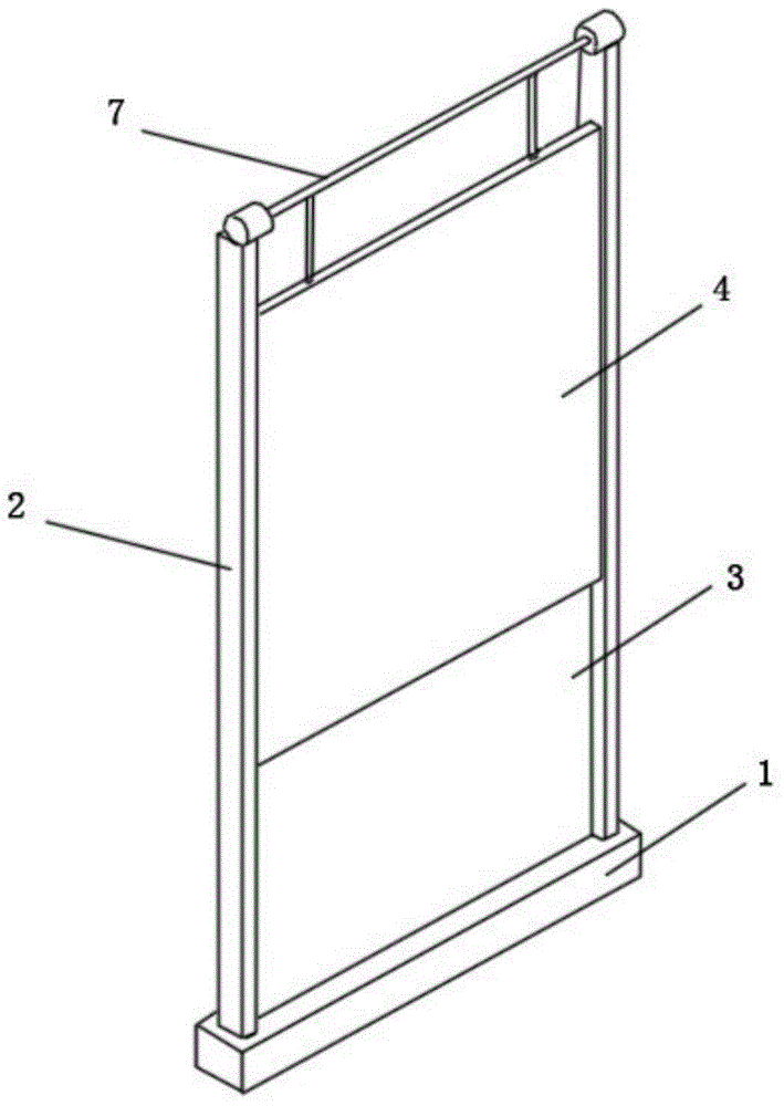
[0050] Embodiment 1: as figure 1 As shown, this embodiment is composed of a base 1, a support frame 2, a fixed sound insulation board 3, a liftable sound insulation board 4, a wind speed sensor 5, a controller 6, a transmission part 7 and a driving part 8, wherein the wind speed sensor 5, The controller 6 and the driver 8 are in figure 1 Not identified in .

[0051] The support frame 2 is fixed on both ends of the base 1 for fixing and supporting the sound insulation board 3 and the movable sound insulation board 4 . At the same time, in order to ensure the structural strength of the sound insulation barrier, the fixed sound insulation board 3 is fixedly connected with the support frame 2 and the base 1 respectively.

[0052] The support frame 2 is provided with a groove, and the liftable sound insulation board 4 slides up and down along the groove to adjust the height of the entire liftable mobile barrier; or, the support frame 2 is provided with convex grooves, and both si...

Embodiment 2

[0060] This embodiment is similar to embodiment 1, and its difference is:

[0061] (1) The transmission part 7 is located under the liftable sound insulation panel 4, and at this time constitutes a "jack-up type", that is, the transmission part 7 controls the lifting of the liftable sound insulation panel 4 in a telescopic manner under the liftable sound insulation panel 4 .

[0062] (2) Since the effect of the wind speed sensor 5 is to accurately and real-time detect the wind speed situation of the environment where the liftable sound insulation barrier is located, especially in coastal areas, when a typhoon comes, the wind speed sensor 5 needs to detect the change of the wind speed in time, And for the controller 6 to respond to environmental changes in time, so the wind speed sensor 5 may not be arranged on the liftable sound insulation barrier, but on an open field close to the liftable sound insulation barrier and without shelter, as long as it can Just meet the above re...

Embodiment 3

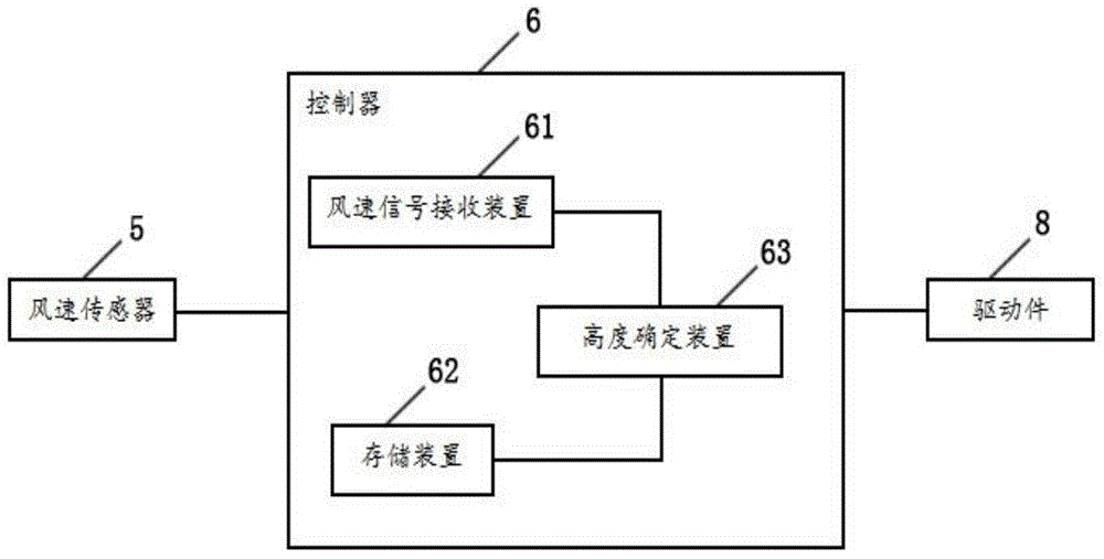
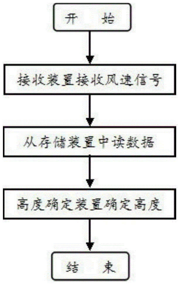
[0065] Such as figure 2 As shown, the controller 6 includes a wind speed signal receiving device 61 , a storage device 62 , and an altitude determination device 63 , and the altitude determination device 63 is connected to the wind speed signal receiving device 61 and the storage device 62 respectively.

[0066] The wind speed signal receiving device 61 is used for receiving the wind speed signal collected by the wind speed sensor 5 .

[0067] The storage device 62 is used for storing each height of the liftable sound insulation panel 4 and the corresponding wind speed critical value.

[0068] Altitude determination device 63, used to compare the size of the wind speed and the critical value of wind speed at the current height, if the wind speed is greater than the critical value of wind speed, then output a control command to drop to the designated height; control instructions.

[0069] In this embodiment, the wind speed critical value is determined by the height of the li...


PUM


Abstract

The invention relates to the field of environmental protection and noise reduction, in particular to a lifting type sound insulation screen based on changes of wind speeds. The screen comprises a base, a supporting frame and a fixed sound insulation board, and is structurally characterized by further comprising a lifting sound insulation board, a wind speed sensor, a controller, a drive part and a transmission part, the fixed sound insulation board is fixedly connected with the base and the supporting frame, the lifting sound insulation board is connected to the supporting frame in a sliding or rolling mode, the lower edge of the lifting sound insulation board is equal to or higher than the lower edge of the fixed sound insulation board, the transmission part is connected with the lifting sound insulation board, the drive part is connected with the transmission part and the controller, and the wind speed sensor is connected with the controller and arranged on the top of the lifting sound insulation screen. The height of the lifting type sound insulation screen is adjusted in time according to the condition of the current wind speed, so that the noise reduction requirement and dual control over structural intensity safety are met under different weathers and different working conditions.

Description

technical field [0001] The invention relates to the field of environmental protection and noise reduction, in particular to a liftable sound insulation barrier based on changes in wind speed. Background technique [0002] With the increasingly stringent national environmental protection policies and the gradual improvement of people's quality of life requirements, noise pollution, as one of the main environmental pollution factors, has been paid more and more attention by environmental protection agencies and polluted people. Therefore, as large-scale industrial and mining enterprises with prominent noise pollution problems, such as power generation enterprises, metallurgical enterprises, petrochemical enterprises, cement enterprises, etc., the pressure to meet environmental protection standards is increasing, and it is urgent to achieve standards through practical and feasible noise control processes. [0003] In the process of selecting the technical route of noise control...

Claims


Application Information

Patent Timeline
Patent Type & Authority Applications(China)
IPC IPC(8): E04B1/84E01F8/00
Inventor 沈吕远
Owner 杭州绿隆环保科技有限公司
Learn More