
Method for restraining myriawatt-class laser welding thick plate upper surface defects

A technology of laser welding and defects, which is applied in the direction of laser welding equipment, welding equipment, manufacturing tools, etc., can solve the problems such as uncontrollable upper surface spatter of weld upper forming quality, poor preheating temperature control, affecting workpiece forming quality, etc. , to achieve the effect of increasing welding penetration performance, reducing the content of solid solution impurities, and reducing the probability of defects

Inactive Publication Date: 2015-05-20
HUNAN UNIV
View PDF12 Cites 13 Cited by
  • Summary
  • Abstract
  • Description
  • Claims
  • Application Information

AI Technical Summary

Problems solved by technology

The disadvantages are: double-sided grooves need to be opened, special fixtures need to be designed, and the efficiency is low; there are many preheating times, and the preheating temperature is not easy to control accurately, which affects the forming quality of the workpiece
The disadvantages are: laser self-fluxing welding, laser wire filling welding, and laser arc hybrid welding are carried out successively, and pre-grooving is required for all of them. The process is too complicated, the equipment is replaced frequently, and the production efficiency is low.
The problem is that although the defects at the bottom of the weld are suppressed, the forming quality of the upper part of the weld and the suppression of spatter on the upper surface cannot be controlled
When the splash is generated, a large amount of splash and metal liquid column are thrown out of the molten pool, resulting in the loss of molten metal and the formation of the upper surface collapse

Method used

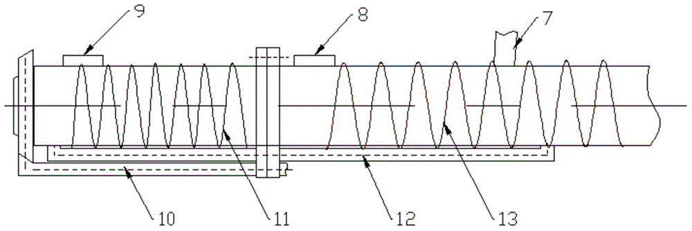
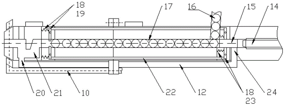

Image

  • Method for restraining myriawatt-class laser welding thick plate upper surface defects
  • Method for restraining myriawatt-class laser welding thick plate upper surface defects
  • Method for restraining myriawatt-class laser welding thick plate upper surface defects

Examples


Embodiment Construction

[0032] Embodiments of the present invention will be described below in conjunction with the accompanying drawings and specific implementation steps.

[0033] The invention provides a method for suppressing defects on the surface of a 10,000-watt laser welded thick plate, the specific steps of which are as follows:

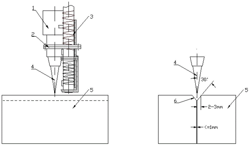
[0034]Step 1: Process the welding plate 5, install the metal particle delivery head 3 on the laser welding head 1, the delivery position of the metal particle 16 is at the rear edge of the unpenetrated welding pool 27, and the metal particle delivery head 3 is perpendicular to the surface of the welding plate 5 with welding direction 29.

[0035] (1) if figure 1 As shown, the present invention uses a high-strength steel plate with a thickness of 10-15 mm as the welding workpiece. The high-strength steel plate uses a butt joint method, and the butt joint gap is less than 1 mm to ensure the accuracy of the weld seam. Chamfering 2-3mm*30.

[0036] (2) if figure 1 ...


PUM

PropertyMeasurementUnit
Diameteraaaaaaaaaa

Abstract

The invention provides a method for restraining myriawatt-class laser welding thick plate upper surface defects. The method comprises the specific steps that 1, a welding plate (5) is machined, a metal particle conveying head (3) is installed on a laser welding head (1), and the conveying position of metal particles (16) is on the rear edge of a welding pool (27) lack of fusion; 2, the metal particles (16) are loaded into the metal particle conveying head (3), and a metal particle heating device is turned on to heat the metal particles (16) to the temperature from 900 DEG C to 1100 DEG C below the melting point; 3, the power of a laser is controlled, a laser beam (4) irradiates the welding plate (5) to form the welding pool lack of fusion, a metal particle conveying system controlled by compressed air is turned on, and the heated metal particles are pushed to the welding pool lack of fusion; 4, an inertia shielding gas annular air blow pipe (10) is turned on, and a laser welding head (1) and the metal particle conveying head (3) synchronously move to complete the welding process. According to the method, material losses generated by some splashes can be complemented, and welding bead subsidence is reduced.

Description

technical field [0001] The invention relates to a method for suppressing partial defects on the upper surface of a 10,000-watt laser welding thick plate, which is mainly used in the laser welding process of a 10,000-watt thick plate to improve the stability of the laser deep penetration welding pool and suppress the spattering of the upper surface Form and reduce the effect of subsurface weld collapse, ultimately improving weld quality. Background technique [0002] Laser technology is a kind of electromagnetic wave with special properties. It is one of the important inventions in the 21st century. Due to the advantages of high brightness and high directionality, good monochromaticity and coherence, laser technology has been developed for decades After that, laser technology has been widely used in the industrial field. Laser welding is one of the important application technologies of laser processing technology. It has broad application prospects and is gradually replacing...

Claims


Application Information

Patent Timeline
IPC IPC(8): B23K26/14B23K26/21
CPCB23K26/123B23K26/24B23K33/004B23K2101/185
Inventor 陈根余李时春周逸凡
Owner HUNAN UNIV
Learn More