Robot welding monitoring system

A robot welding and monitoring system technology, applied in welding equipment, auxiliary welding equipment, welding / cutting auxiliary equipment, etc. Problems such as the path not being in the best state can save the need for manual confirmation, improve the welding effect, and improve the welding efficiency.

Inactive Publication Date: 2015-05-20
国融新兴投资有限公司
View PDF7 Cites 10 Cited by
  • Summary
  • Abstract
  • Description
  • Claims
  • Application Information

AI Technical Summary

Problems solved by technology

[0004] 1. The working conditions of the welding head cannot be directly observed, and the weld seam can only be inspected after the workpiece is welded;
[0005] 2. During the welding process, the working status of the equipment inside the safe room cannot be observed;
[0006] 3. Confirming whether the workpiece is installed in place depends entirely on manual determination. Due to accidental operation errors, inaccurate placement will occur, and it is impossible to ensure that the workpiece can be accurately installed in place every time, and the welding quality cannot be guaranteed, and even scrapped parts will be generated;
[0007] 4. The working path of the robot is not optimal;
[0008] 5. The working environment of the welding head is not in the best condition

Method used


Image

  • Robot welding monitoring system
  • Robot welding monitoring system
  • Robot welding monitoring system

Examples


Embodiment 1

[0037] This embodiment provides a robot welding technology, in particular a robot welding monitoring system.

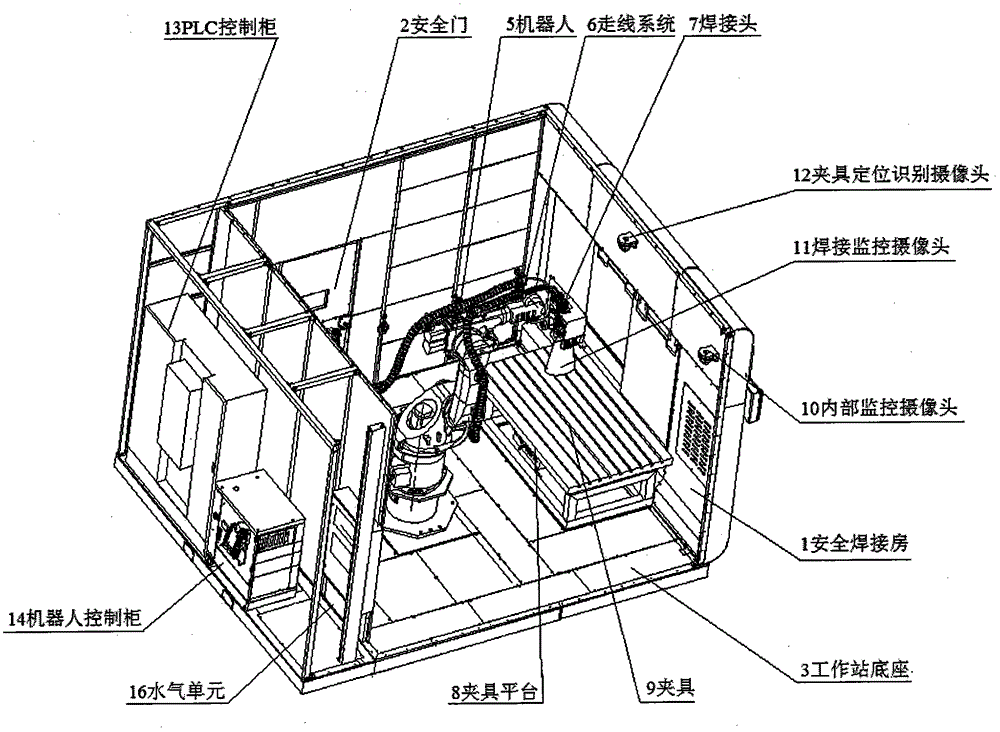
[0038] The robot welding monitoring system is composed of monitoring system, welding system, security system and control system, and the four are electrically connected to each other, among which:

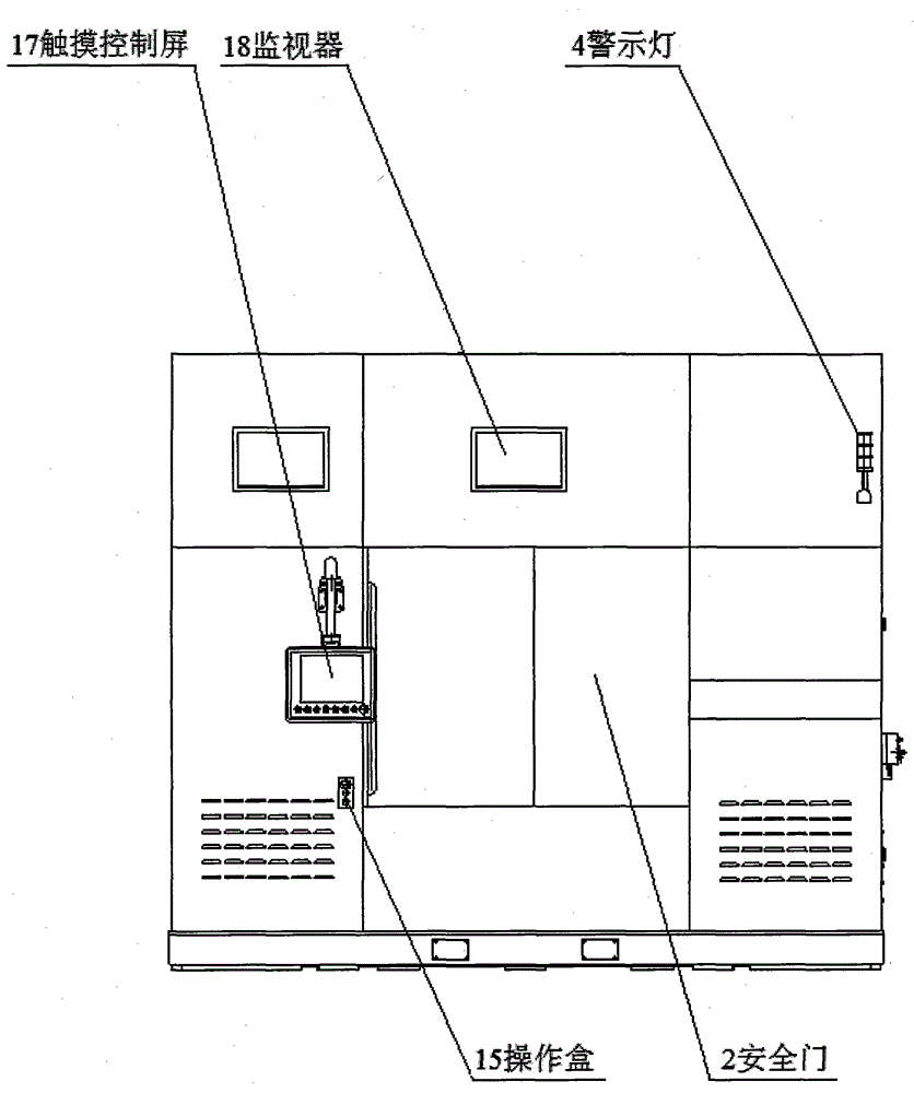
[0039] The security system consists of a safety welding room 1, a safety door 2, a workstation base 3, and a warning light 4; the safety welding room 1, safety door 2, and the workstation base 3 form a closed working space; the monitoring system and welding system are arranged in the safety welding room 1 , the control system is arranged on the periphery of the safety welding room 1; the safety door 2 and the warning light 4 are respectively arranged on the side wall of the safety welding room 1;

[0040] The welding system consists of a robot 5, a wiring system 6, a welding head 7, a fixture platform 8, and a fixture 9. The robot 5 is connected to the welding head 7 throu...

Embodiment 2

[0057] In this embodiment, the structure, functions and expected technical effects are the same as those in Embodiment 1, except that the common switch door is used instead of the safety door.

Embodiment 3

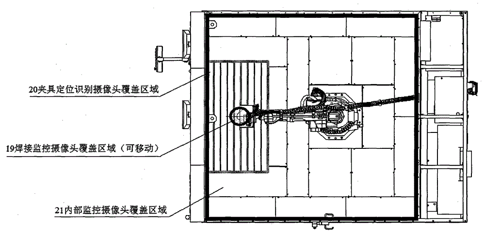
[0059] In this embodiment, except that the jig is not used to locate and identify the camera 12 , other structures, functions, and expected technical effects are the same as those in Embodiment 1. This embodiment does not have the function of intelligently identifying and detecting whether the workpiece is installed in place, and manual confirmation is required.


PUM


Abstract

A robot welding monitoring system is composed of a monitoring system, a welding system, a security system and a control system which are electrically connected. An internal monitoring camera 10 is used for observing the working state of equipment in a welding room, and a welding monitoring camera 11 can observe the working environment of a welding head 7 and the condition of a weld pool. A clamp positioning and recognizing camera 12 has a recognition function and can judge whether a workpiece is installed in place according to the position change of the workpiece. The welding system, the monitoring system, the control system and the security system are integrated to form the robot laser welding monitoring system. The four systems can be organically combined into a whole to form a monitoring network without any dead corner, the condition in the welding safety room can be monitored in real time, the welding efficiency and welding effect of a whole work station are improved, and laser injuries are avoided due to the fact that people do not make direct contact with laser during demonstration and debugging.

Description

technical field [0001] The invention relates to the technical field of robot welding, and in particular provides a robot welding monitoring system. Background technique [0002] With the rapid development of my country's industry, welding robots should be widely used in many fields such as machinery, automobiles, ships, and aerospace manufacturing. The application of welding robots is mainly to adapt to higher standard welding requirements, meet stricter indicators, and provide more accurate welding technology solutions. Therefore, in the daily application of welding robots, it is necessary to provide a complete monitoring system to monitor the welding process in real time, and stop the operation immediately if any problems are found, so as to ensure the welding quality and effectively avoid safety accidents caused by an operation. [0003] At present, most of the domestic laser welding fields are in a sealed environment, and the assembly is mainly confirmed by manual work....

Claims


Application Information

Patent Timeline
Patent Type & Authority Applications(China)
IPC IPC(8): B23K37/00
Inventor 张勇滕文龙
Owner 国融新兴投资有限公司
Why Eureka
Try Eureka