Low-stress self-adaptive machining method and process equipment
A processing method and self-adaptive technology, applied in metal processing equipment, metal processing mechanical parts, positioning devices, etc., can solve the problems of low processing accuracy, cumbersome processing technology, and shortened life of parts.
- Summary
- Abstract
- Description
- Claims
- Application Information
AI Technical Summary
Problems solved by technology
Method used
Image
Examples
Embodiment 1
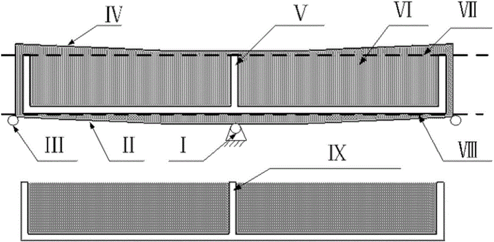
[0071] Such as figure 1 shown.
[0072] A low stress processing method comprising the steps of:
[0073] Step 1, according to the shape of the part, such as figure 1 The part Ⅴ shown in the figure is to fix the machining coordinate system unchanged, and reasonably arrange the positions of the fixed clamping points. Generally, the edge of the center position of the part or the position with a small deformation amount is selected; figure 1 For the part Ⅴ shown, select the center position as the fixed clamping point, such as figure 1 I shown;
[0074] Step 2, design the position of the mobile clamping point of the part, and process the process table, such as figure 1 As shown, the deformation on both sides of the part deformation is relatively large, so the two sides are selected as the moving clamping point as shown in figure 1 As shown in Ⅲ;
[0075] Step 3, according to the height of the process table, select a suitable installation base, fix the installation base on the...
Embodiment approach
[0082] 1. Adaptive clamping platform.
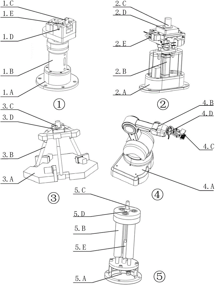
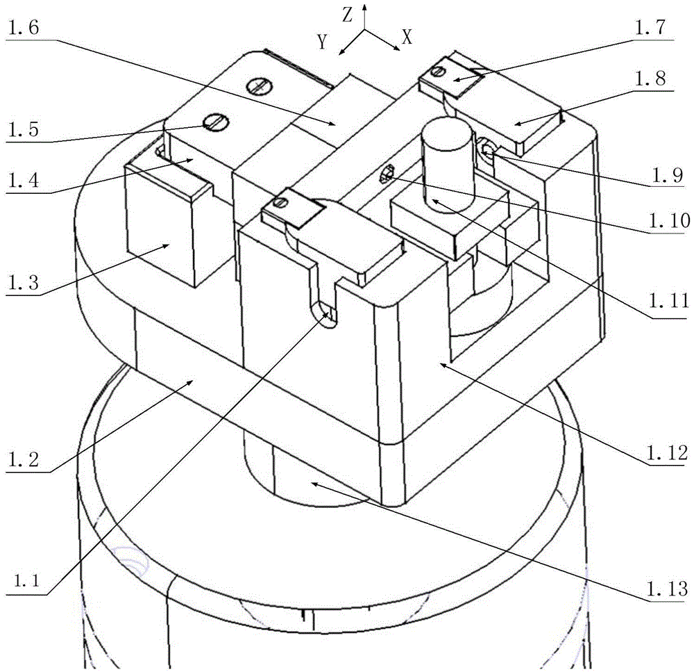
[0083] Such as figure 2 , 3 , 4, and 10, the implementation of the self-adaptive clamping platform is:
[0084] The middle edge of the part is a fixed clamping position, and 5 adaptive clamping platforms are fixed on each side. The adaptive clamping platform is connected to the workbench through the installation base 1.C, and is connected by screws; the installation base 1.C is connected by screws. Connect with the movement mechanism; after the self-adaptive clamping platform is installed, adjust the position of the lifting column 1.26 through the air / liquid device, so that the process table is in contact with the device. The cavity 41.33 is fed with high-pressure gas / liquid, and the pressure difference generated by the cavity 41.33 and the cavity 21.20 generates a pulling force on the piston rod 1.29, and generates a clamping force on the parts through the U-shaped guide rail 1.4. After all clamps, record the initial value of each f...
Embodiment 3
[0098] Low-stress processing method control system frame and flow chart of the present invention are as follows Figure 15 As shown, it includes the following steps:
[0099] Step 1, the overall control module sets the working position H of the clamping point 0 , to ensure that after the part is clamped, the clamping point has a movable margin in all directions. For example, the maximum height displacement of the clamping point movement is H m , then H 0 Usually set to H m / 2 can also be determined empirically. The single control module adjusts the clamping point to the specified position after receiving the command, and then completes the clamping of the parts;
[0100] Step 2, after the clamping is completed, read the initial measurement value F of the force sensor 0 . Judging whether the spindle of the machine tool starts to rotate, if the spindle rotates, the overall control module sends a command to the individual control module to enter the adjustment state; other...
PUM
 Abstract
Description
Claims
Application Information
 - R&D
- Intellectual Property
- Life Sciences
- Materials
- Tech Scout
- Unparalleled Data Quality
- Higher Quality Content
- 60% Fewer Hallucinations
Browse by: Latest US Patents, China's latest patents, Technical Efficacy Thesaurus, Application Domain, Technology Topic, Popular Technical Reports.
© 2025 PatSnap. All rights reserved.Legal|Privacy policy|Modern Slavery Act Transparency Statement|Sitemap|About US| Contact US: help@patsnap.com


