Coaxial digital holographic microscopy imaging device and method for detecting glass subsurface defect

A digital holographic microscope and imaging device technology, applied in the direction of measuring devices, instruments, scientific instruments, etc., can solve the problems of inaccurate estimation, difficult resolution and inspection of sub-surface defects, etc., and achieve high adaptability, simple structure and high performance stable effect

Inactive Publication Date: 2015-05-20
NANJING UNIV OF SCI & TECH
View PDF7 Cites 14 Cited by
  • Summary
  • Abstract
  • Description
  • Claims
  • Application Information

AI Technical Summary

Problems solved by technology

The traditional method is to calculate the depth according to the relationship between surface roughness, abrasive size and other parameters, and the subsurface defect depth, and then remove the defect layer by magnetorheological polishing technology, but the actual depth of the defect is often greater than This calculated value leads to inaccurate estimation of this method; in recent years, researchers at home and abroad have proposed techniques such as total internal reflection mirror imaging, low-coherence tomography, and confocal microscopy imaging to obtain cross-sectional or depth images of subsurface defects. , but due to their respective limitations, it is difficult to meet the requirements for inspection of subsurface defects in terms of resolution or depth, and it is necessary to obtain a three-dimensional image of the sample through mechanical scanning

Method used


Image

  • Coaxial digital holographic microscopy imaging device and method for detecting glass subsurface defect
  • Coaxial digital holographic microscopy imaging device and method for detecting glass subsurface defect

Examples


Embodiment 1

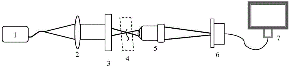
[0024] The He-Ne laser 1 emission wavelength described in the present embodiment is the monochromatic light of 632.8nm; Sample 3 is the glass that has subsurface damage, and damage size is micron or submicron order of magnitude; The numerical aperture of microscopic objective lens 5 is 0.55; the charge coupler 6 is an area coupler.

[0025] The present invention is based on the coaxial digital holographic microscopic imaging device and the method for detecting glass subsurface defects, including the following steps:

[0026] Step 1, He-Ne laser 1 emits monochromatic light with a wavelength of 632.8nm, irradiates on the collimating objective lens 2, and adjusts the collimating objective lens 2 so that the emitted light hits the sample 3 evenly on the glass with subsurface defects;

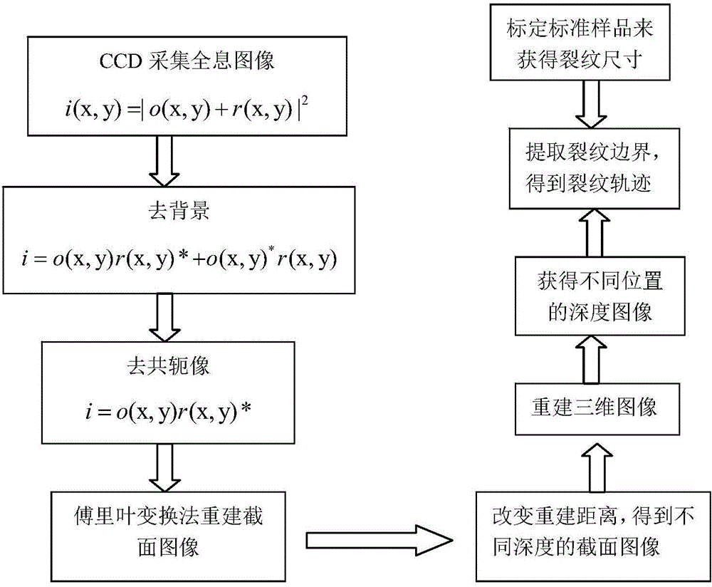
[0027] Step 2, transmit the light beam of the sample 3, part of the light is scattered by the sample as the sample light, and the other part is not scattered as the reference light, and the two ligh...


PUM


Abstract

The invention discloses a coaxial digital holographic microscopy imaging device and a method for detecting a glass subsurface defect. The coaxial digital holographic microscopy imaging device can realize imaging based on the double-beam interference principle and comprises a He-Ne laser, a collimating lens, a sample, a microobjective and a charge coupled device, which share an optical axis and are arranged sequentially in a light path direction, wherein the signal output end of the charge coupled device is connected with a computer, the He-Ne laser emits laser light, the laser light passes through the collimating lens to form a collimated light beam, the collimated light beam is irradiated on the sample, scattered light from the sample is sample light, and un-scattered light is reference light, the two light beams can form a hologram after being overlapped on the working surface of the microobjective, the hologram is imaged on the charge coupled device to be amplified and input into the computer by the microobjective, and the computer can reconstruct images of the sample in different depth according to the received amplified hologram. The coaxial digital holographic microscopy imaging device has a simple and stable structure and does not require mechanical scanning, and a three-dimensional image of the sample can be reconstructed with the hologram acquired once.

Description

technical field [0001] The invention relates to the field of digital holography (Digital Holography, DH) imaging technology, in particular to a coaxial digital holography microscopic imaging device and a method for detecting glass subsurface defects. Background technique [0002] Digital Holography (DH) imaging is a non-contact and non-destructive imaging technology based on traditional holography. In 1976, Goodman and Lawrence clearly proposed digital holography. By 1994, Schnars and Jueptner used charge coupled devices (CCD) to receive holographic images for the first time, and digitally reconstructed the collected signals by computer. The advantage of digital holography is that the holographic image is recorded by CCD, which simplifies the operation steps and greatly reduces the operation time of holographic imaging; the digital reconstruction is completed by computer, and the amplitude and phase information of the sample are obtained at the same time; no mechanical scann...

Claims


Application Information

Patent Timeline
Patent Type & Authority Applications(China)
IPC IPC(8): G01N21/958G01N21/01
Inventor 高万荣伍秀玭何勇廖九零张运旭卞海溢陈朝良朱越
Owner NANJING UNIV OF SCI & TECH
Why Eureka
Try Eureka