Oil-separation recovery combination apparatus

A combined equipment and oil separation technology, applied in the direction of grease/oily substance/float removal device, water/sludge/sewage treatment, liquid separation, etc. Low efficiency and other problems, to achieve the effect of small footprint, good water quality conditions, simple and compact structure

Active Publication Date: 2015-05-27
江苏江大环境工程有限责任公司
View PDF5 Cites 0 Cited by
  • Summary
  • Abstract
  • Description
  • Claims
  • Application Information

AI Technical Summary

Problems solved by technology

[0004] Traditional gravity separation oil separation facilities are usually single separation oil separation facilities, and most of them are advection type oil separation tanks or single inclined plate type oil separation tanks, which are mainly used to separate floating oil and disperse oily light oil substances; for heavy oil Oil separation and recovery of similar substances are often additionally treated by adding separate treatment facilities. At the same time, the oil floating on the upper layer of the gravity separation oil separation facility often needs to be cleaned manually, the equipment operation intensity is high, and the oil removal efficiency is low; at the same time, the traditional oil separation facilities The treatment of light oil is usually carried out by flocculation reaction precipitation and oil separation and oil removal, which is not conducive to green circular economy
[0005] Traditional oil separation facilities and oil storage facilities are often independent and split facilities with scattered layout, large total area and low land utilization rate

Method used


Image

  • Oil-separation recovery combination apparatus
  • Oil-separation recovery combination apparatus
  • Oil-separation recovery combination apparatus

Examples


Embodiment Construction

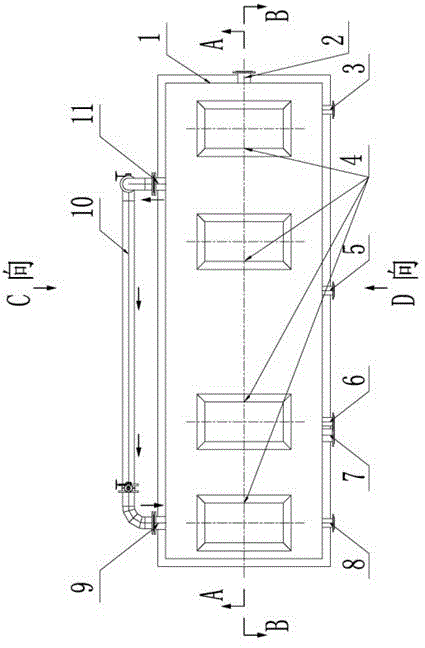
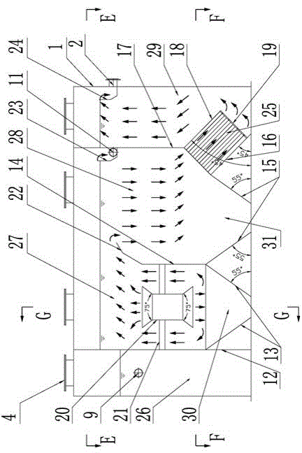
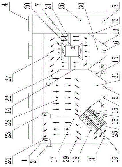
[0041] Such as Figure 1~7 As shown, a schematic diagram of a new type of oil separation combined equipment is provided for the technical solution of the patent of the invention.

[0042] The sewage produced by an enterprise contains a large amount of heavy oil, slick oil, and partially dispersed oily light oil substances. If the oily substances enter the subsequent biochemical treatment system without treatment, they will adhere to the surface of the activated sludge and inhibit the microbial growth in the biochemical treatment unit. Normal growth will directly affect the operation of the biochemical system. In severe cases, it will destroy the sludge activity of the activated sludge system and affect the biochemical treatment effect. This oily wastewater needs to be pretreated with oil separation.

[0043] The equipment includes four unit components of the primary oil barrier recovery chamber 27, the secondary oil barrier recovery chamber 28, and the oil collection chamber 26 and...


PUM

PropertyMeasurementUnit
angleaaaaaaaaaa
pore sizeaaaaaaaaaa
pore sizeaaaaaaaaaa

Abstract

The invention relates to a sewage treatment apparatus, particularly an oil-separation recovery combination apparatus capable of simultaneously recovering heavy oil and light oil. A primary oil-separation recovery heavy oil apparatus, a secondary oil-separation recovery light oil apparatus, an oil collection apparatus and the like are combined into a serial modular combination apparatus, and all the apparatuses are separated by partitions. The oil-separation recovery combination apparatus can simultaneously recover heavy oil, floating oil and partial dispersed light oil substances in sewage, and is beneficial to green circular economy.

Description

Technical field [0001] The patent of the invention relates to a sewage treatment equipment, in particular to an oil separation recovery combined equipment that can recover heavy oil and light oil at the same time. Background technique [0002] At present, some organic pollutants in industrial oily sewage often exist in the sewage as oil phase. These oil substances are largely in the form of heavy oil, slick oil, and dispersed oil light oil. If this oil substance is treated effectively Not good, it is often very easy to affect the subsequent sewage treatment process. [0003] Gravity separation of heavy oil and slick oil, dispersed oil light oil is the most widely used and most practical oily wastewater treatment process. This method can be used to recover slick oil, partially dispersed oil light oil and heavy oil in sewage. [0004] Traditional gravity oil separation facilities are usually single oil separation facilities, and most of them are advection oil traps or single sloping p...

Claims


Application Information

Patent Timeline
Patent Type & Authority Applications(China)
IPC IPC(8): C02F9/02C02F1/40
CPCC02F1/40C02F9/00
Inventor 徐亮宋坤祥王开鹏
Owner 江苏江大环境工程有限责任公司
Why Eureka
Try Eureka