Solid grain block heat accumulating type multi-generation unit and trolley

A solid block and polygeneration technology, which is applied in the direction of motor vehicles, thermal storage equipment, transportation objects, etc., can solve the problems of unrealistic storage and waste

Inactive Publication Date: 2015-05-27
CHENGDU AONENGPU TECH
View PDF14 Cites 0 Cited by
  • Summary
  • Abstract
  • Description
  • Claims
  • Application Information

AI Technical Summary

Problems solved by technology

[0006] The energy storage power station uses electric energy for storage, especially the electric energy composed of wind power and photovoltaic, because it cannot be stored, it has to be discarded in large quantities, causing a lot of waste

Method used


Image

  • Solid grain block heat accumulating type multi-generation unit and trolley
  • Solid grain block heat accumulating type multi-generation unit and trolley

Examples


Embodiment 1

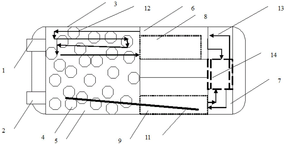
[0049] Embodiment 1, fixed solid block thermal storage polygeneration unit

[0050] figure 1 The fixed solid block heat storage polygeneration unit shown is composed of container 3, heat storage material 4, polygeneration devices (8, 9, 10), and control system 14; heat storage material 4 and polygeneration unit ( 8, 9, 10) and the control system 14 are set in the container 3; there are three cavities inside the container 3, a heat storage material chamber 5, a polygeneration device chamber 6, and another control system Chamber 7, set solid granules in the thermal storage material chamber, which is composed of 30% iron oxide, 40% heat-conducting cement, and 30% sand, which are processed into hexagonal granules and placed in the polygeneration chamber 6 The power generation device 8 and the refrigeration device 9 are provided. The power generation device 8 and the heat storage material complete the heat energy exchange through the fluid heat exchange 12 system, and the heat ene...

Embodiment 2

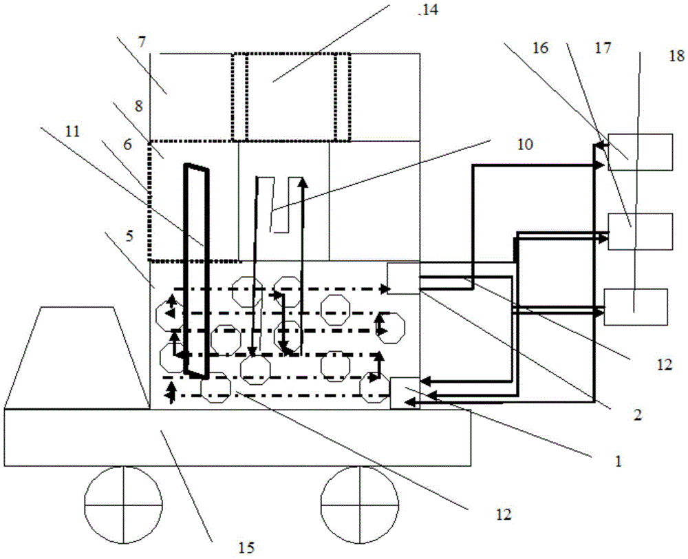
[0054] Embodiment 2, mobile solid block thermal storage polygeneration unit

[0055] figure 2 figure 1The mobile solid block heat storage polygeneration unit shown is composed of transportation equipment 15, container 3, heat storage material 4, polygeneration devices (8, 9, 10), and control system 14; The cogeneration units (8, 9, 10) and the control system 14 are set in the container 3; the interior of the container 3 is provided with three cavities, a heat storage material chamber 5, a polygeneration device chamber 6, and another One is the control system chamber 7, and a solid block is arranged in the heat storage material chamber, and the solid block is composed of fired ceramic blocks, and a power generation device 8 and a water heating device 10 unit are arranged in the polygeneration chamber 6, The power generation device 8 and the heat storage material complete the heat energy exchange through the circulating heat pipe 11 system, and provide the heat energy to the ...


PUM


Abstract

The utility model provides a solid grain block heat accumulating type multi-generation unit realizing low-cost and high efficient energy utilization via mutual use of various energies and heat accumulation via a heat accumulator, and in particular realize effective utilization of waste heat and low ebb power. Solid grains are employed as heat accumulating material; the solid grains are transferred to a container; at least three chambers are formed in the container, one heat accumulating chamber, one multi-generation component chamber and one control system chamber; a heat exchanging component is arranged between the solid grains and a multi-generation component; heat is exchanged between heat energy and the solid grains in the container via the fluid; and when heat energy is required, heat energy is used via the fluid. The utility model also aims to provide a solid grain block heat accumulating type multi-generation unit trolley moving the heat accumulator to an area requiring heat energy for utilization; and movable heat accumulation can be achieved.

Description

technical field [0001] The present invention relates to thermal energy utilization, in particular to a system for utilizing energy in the form of thermal energy and storing it. Background technique [0002] The heat accumulator is a device for storing thermal energy, and the existing heat accumulators are steam type and liquid heat accumulators; [0003] In the field of industrial energy conservation, waste heat is recovered and stored, usually using phase change technology for heat storage, and in the low temperature field using ice storage technology for heat storage; [0004] In the field of solar energy, molten salt is used to store heat. Although molten salt can achieve high temperature storage, it needs heat energy to heat it because it needs to be transformed from solid to liquid. At the same time, there are problems with the toxicity, economy, and safety of molten salt. , so the use of molten salt heat storage is limited. [0005] In the field of solar energy, air ...

Claims


Application Information

Patent Timeline
Patent Type & Authority Applications(China)
IPC IPC(8): F28D20/00B60P3/00
CPCY02E60/14
Inventor 李建民
Owner CHENGDU AONENGPU TECH
Why Eureka
Try Eureka