High-energy beam additive manufacturing method and equipment with high powder raw material utilization rate

An additive manufacturing, powder raw material technology, applied in the field of high-energy beam additive manufacturing, can solve problems such as hindering the development of SLM technology and EBSM technology, low powder utilization rate, excessive redundant powder, etc., to enhance humanization and green environmental protection Features, dust pollution reduction, the effect of simplifying the mechanical structure of the equipment

Active Publication Date: 2015-06-03
HUAZHONG UNIV OF SCI & TECH +1
View PDF8 Cites 32 Cited by
  • Summary
  • Abstract
  • Description
  • Claims
  • Application Information

AI Technical Summary

Problems solved by technology

However, the technical defect of too much redundant powder becomes more and more serious with the continuous increase of the forming limit size and the forming cylinder space
[0006] To s

Method used


Image

  • High-energy beam additive manufacturing method and equipment with high powder raw material utilization rate
  • High-energy beam additive manufacturing method and equipment with high powder raw material utilization rate
  • High-energy beam additive manufacturing method and equipment with high powder raw material utilization rate

Examples


Embodiment 1

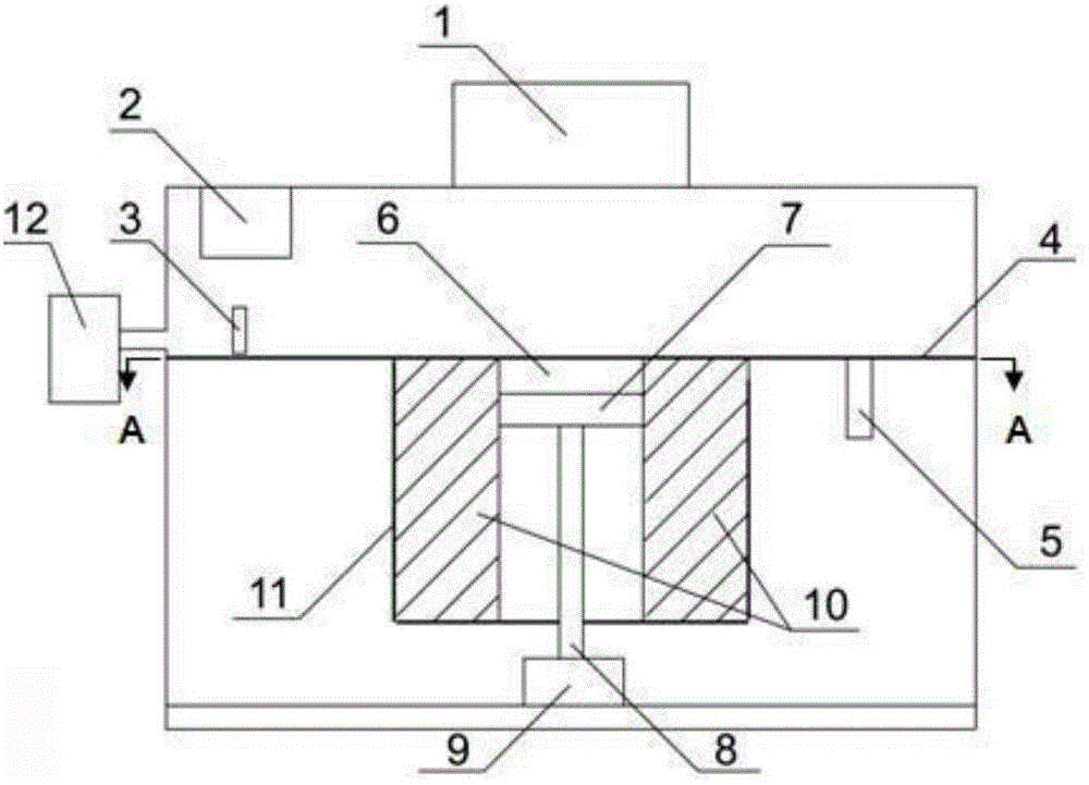
[0048] When using high-energy beam additive manufacturing technology for new product development, it often occurs that the vertical projection size of the formed metal component on the working plane is relatively small relative to the format of the forming cylinder. At this time, the first forming method involved in the present invention is used. The reconfigurable high-energy beam additive manufacturing device of cylinder can significantly improve the powder utilization rate under the premise of ensuring the precision and performance of components.

[0049] As shown in Figure 1, the first high-energy beam additive manufacturing device involved in the present invention includes a high-energy beam scanning module 1, a powder storage chamber 2, a powder spreader 3, a working plane 4, a powder recovery cylinder 5, a molding cylinder 11, Control system 9 and gas purification system 12.

[0050] The control system 9 is used to regulate the coordinated work of the high-energy beam s...

Embodiment 2

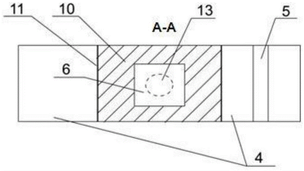
[0068] If the metal part is a hollow frame structure with a larger size and equal cross-section (that is, a large-sized part with a circular through-hole, a square through-hole or other through-holes with a constant cross-sectional area in the height direction), if the traditional SLM or For EBSM forming, a large amount of alloy powder needs to be used to fill the inside of the through hole, which greatly reduces the utilization rate of the powder. At this time, the above-mentioned problems can be better solved by adopting the second reconfigurable high-energy beam additive manufacturing method and device involved in the present invention.

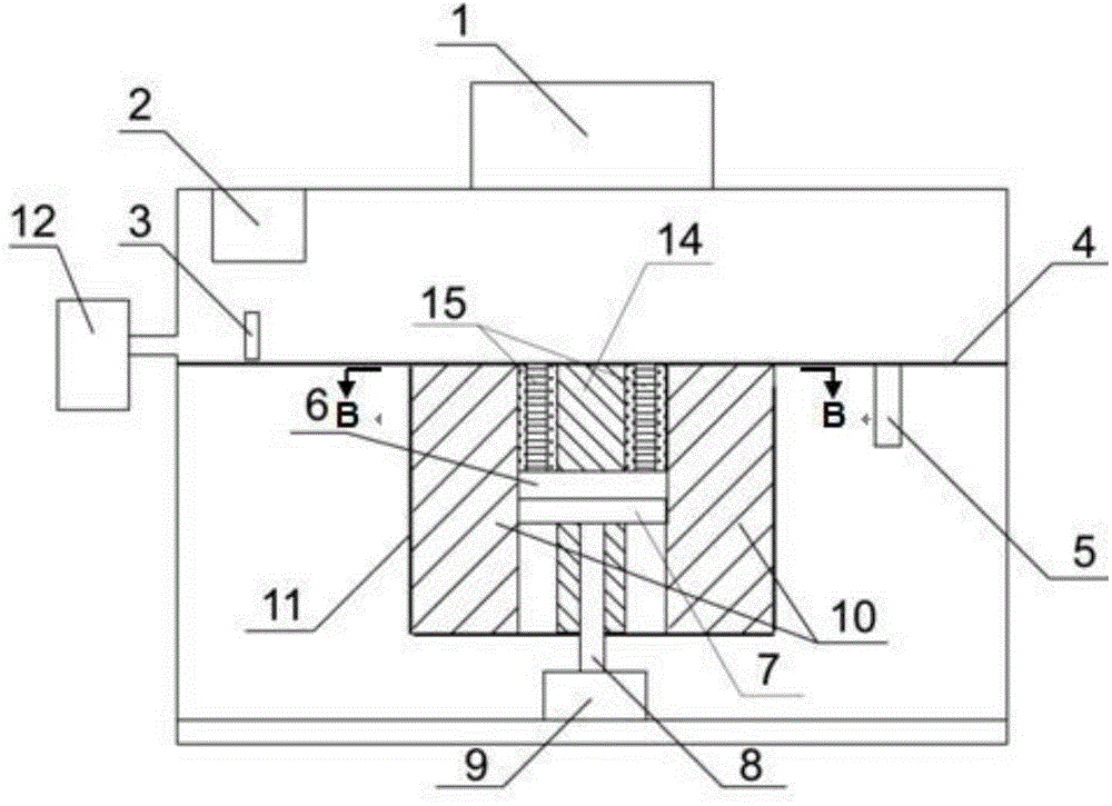
[0069] Without loss of generality, assuming that the metal part to be formed is a large-sized cylindrical ring belonging to one of the above-mentioned equal-section hollow frame structures, the second specific embodiment of the high-energy beam additive manufacturing device involved in the present invention as shown in picture 2. The devi...

Embodiment 3

[0088] If the horizontal cross-sectional area of ​​the through hole contained in the hollow frame member gradually decreases with the increase of the number of processing layers, then when the device involved in Embodiment 2 is used for additive manufacturing, the horizontal cross-sectional area of ​​the inner insert 14 must be smaller than the specified The minimum cross-sectional area of ​​the through hole of the corresponding component can avoid interference between the internal insert 14 and the laser scanning path, thereby ensuring smooth processing. In this case, the inner insert 14 can only occupy a small part of the space inside the through hole of the component, and the remaining space still needs to be filled with redundant powder. In order to realize the forming of such components under the condition of ensuring high powder utilization rate, the structure of the internal insert 14 and its installation method involved in Embodiment 2 can be improved, thereby forming t...


PUM


Abstract

The invention discloses a high-energy beam additive manufacturing method and equipment with high powder raw material utilization rate. The method comprises the following step of according to the outline shape of a to-be-molded metal component slice, determining the internal structure of a molding cylinder, wherein metal powder of each powder paving layer is only positioned in an area corresponding to the outline shape of the to-be-molded metal component slice, so that the using amount of the metal powder is greatly reduced, and the function and effect of manufacturing the high-energy beam increasing material is improved. The equipment comprises one or more molding cylinders, wherein the internal structures of the molding cylinders are matched with the outline shape of the to-be-molded metal component slice. Due to the fact that an insert and a special-shaped substrate which adapts to the outline shape of the metal component slice are used, rebuilding of the molding cylinders for different metal component structure characteristics is realized, and the defect that redundant powder is too much in the traditional high-energy beam increasing material manufacturing process is successfully avoided. High-quality and High-effective molding of various metal components with complex structures and different sizes can be finished under the condition of high powder utilization rate.

Description

technical field [0001] The invention belongs to the technical field of high-energy beam additive manufacturing, and in particular relates to a high-energy beam additive manufacturing method and equipment with high utilization rate of powder raw materials. Background technique [0002] In recent years, high energy beam additive manufacturing technology (also known as high energy beam 3D printing technology) of metal parts has developed rapidly. Among them, the basic principles of selective laser melting technology (Selective Laser Melting, SLM technology for short) and electron beam selective melting technology (EBSM technology for short) based on powder bed laying can be summarized as follows: The alloy powder is evenly laid on the surface of the substrate, and then according to the digital structure and slicing data of the metal parts to be processed, the metal powder is melted point by point and line by line by laser or electron beam, and the melted alloy powder is cooled ...

Claims


Application Information

Patent Timeline
IPC IPC(8): B22F3/105
CPCY02P10/25
Inventor 曾晓雁魏恺文王泽敏朱海红陈立新
Owner HUAZHONG UNIV OF SCI & TECH
Why Eureka
Try Eureka