Laminated double-sided multi-serpentine microchannel reforming hydrogen production reactor

A reforming hydrogen production and microchannel technology, applied in hydrogen, chemical instruments and methods, inorganic chemistry, etc., can solve problems such as unfavorable catalyst coating, achieve the effect of increasing retention time, increasing conversion rate, and realizing scale expansion

Inactive Publication Date: 2015-06-03
ZHEJIANG UNIV
6 Cites 21 Cited by

AI-Extracted Technical Summary

Problems solved by technology

This reactor contains three layers of plate-shaped reaction carriers, all of which have a micro-boss array structure, forming two upper and lower channels. Among them, the upper channel is a hydrogen production channel by catalytic reforming, and the lower channel is a combustion channel. The reactor can operate by self-heating Hydrogen production, but the surface of the reaction carrier is relatively smooth, which is not conducive to the coating of the catalyst
[0005...

Method used

Thus, stacked multi-serpentine microchannel reforming hydrogen production reactor of the present invention, through the design of double-sided multi-serpentine microchannel reaction carrier sheet, can increase the specific surface area of ​​reaction carrier sheet, improve the performance of catalyst Adhesion, an...

Abstract

The invention discloses a laminated double-sided multi-serpentine microchannel reforming hydrogen production reactor which comprises an upper cover board, a lower cover board, an evaporation plate, a plurality of upper reforming plates and lower reforming plates, wherein the plurality of upper reforming plates are arranged between the evaporation plate and the lower reforming plates; a flexible graphite pad is arranged between any two adjacent upper reforming plates; an evaporation cavity is formed in the upper surface of the evaporation plate; an inlet drainage cavity and an outlet drainage cavity, which are communicated with each other, are symmetrically connected with two sides of the evaporation cavity respectively; reaction cavities are formed in the centers of the upper reforming plates and the lower reforming plates; the inlet drainage cavity and the outlet drainage cavity, which are communicated with each other, are symmetrically connected with two sides of each reaction cavity respectively; reaction carrier sheets are arranged in the reaction cavities of the upper reforming plates and the lower reforming plates; and groove structures with a plurality of serpentine microchannels are symmetrically formed in the upper surfaces and the lower surfaces of the reaction carrier sheets respectively up and down. According to the laminated double-sided multi-serpentine microchannel reforming hydrogen production reactor, the specific surface area of the reaction carrier sheets can be significantly increased; adhesion of a catalyst is improved; and the reaction pressure drop can be effectively reduced, so that the alcohol conversion rate and the hydrogen production speed are improved.

Application Domain

Technology Topic

Image

  • Laminated double-sided multi-serpentine microchannel reforming hydrogen production reactor
  • Laminated double-sided multi-serpentine microchannel reforming hydrogen production reactor
  • Laminated double-sided multi-serpentine microchannel reforming hydrogen production reactor

Examples

  • Experimental program(1)
  • Effect test(1)

Example Embodiment

[0035] The present invention will be further described in detail below in conjunction with the drawings and specific embodiments.
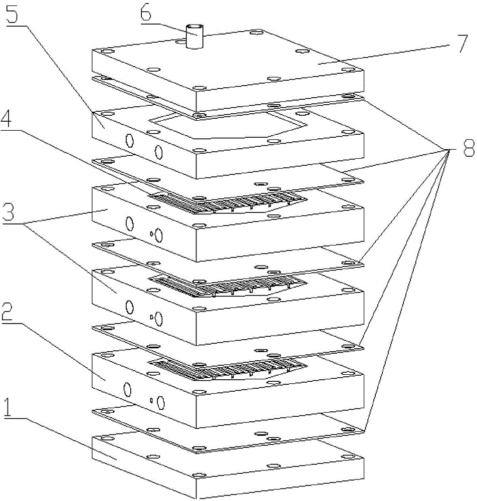
[0036] Such as figure 1 As shown, the present invention includes an upper cover plate 7, a lower cover plate 1, and an evaporation plate 5, a plurality of upper reforming plates 3, and a lower reforming plate that are sequentially sealed and installed between the upper cover plate 7 and the lower cover plate 1. 2. The number of the upper reforming plate 3 is 2-9, and multiple upper reforming plates 3 are installed between the evaporation plate 5 and the lower reforming plate 2. The upper cover plate 7, the lower cover plate 1, the evaporation plate 5, A flexible graphite gasket 8 is provided between any two adjacent mounting surfaces of the plurality of upper reforming plates 3 and lower reforming plates 2, and each plate is connected and assembled by bolts.
[0037] Such as figure 1 As shown, the upper cover 7 is equipped with an inlet pipe 6, such as Figure 7 As shown, the lower cover 1 is equipped with an outlet pipe 16; Figure 4 As shown, the upper surface of the evaporation plate 5 is provided with an evaporation cavity 11, the two sides of the evaporation cavity 11 are symmetrically connected with an inlet drainage cavity 12 and an outlet drainage cavity 14, respectively, and the outlet drainage cavity 14 is provided with an evaporation cavity outlet through hole 13; Figure 5 with Image 6 As shown, the upper surface center of the upper reforming plate 3 and the lower reforming plate 2 are both provided with a reaction chamber 18, and the reaction chamber 18 of the upper reforming plate 3 and the lower reforming plate 2 are both installed with a reaction carrier sheet 4, the reaction carrier Thin plate 4 is a rectangular plate, such as image 3 As shown, the upper surface and the lower surface are symmetrically opened up and down with groove structures having the same structure and containing a plurality of serpentine microchannels 10 arranged in parallel, and the serpentine microchannels 10 between the upper and lower surfaces are distributed in mirror symmetry.
[0038] The upper reforming plate 3 and the reaction chamber 18 of the lower reforming plate 2 are connected symmetrically on both sides of the inlet drainage cavity 12 and the outlet drainage cavity 14 respectively. The inlet drainage cavity 12 of the upper reforming plate 3 is provided with a steam flow The inlet through hole 15, the outlet diversion cavity 14 of the upper reforming plate 3 is provided with an upper reforming plate outlet through hole 19 for steam circulation, and the outlet diversion cavity 14 of the lower reforming plate 2 is provided with a lower weight for steam outflow. The entire board outlet through hole 20.
[0039] The upper cover plate 7, each upper reforming plate 3, and the upper reforming plate 3 have the inlet drainage chambers 12 on the same side, and the outlet drainage chambers 14 are on the same side; the evaporation chamber outlet through hole 13 is the uppermost reforming plate The inlet through holes 15 of 3 are correspondingly communicated, and the upper reformer plate outlet through holes 19 of the lowermost upper reformer plate 3 are correspondingly communicated with the inlet drainage cavity 12 of the lower reformer plate 2.
[0040] Such as Figure 8 As shown, the mixed liquid enters from the inlet pipe 6 of the upper cover plate 7, and then passes through the inlet drainage cavity 12, the evaporation cavity 11, and the outlet drainage cavity 14 of the evaporation plate 5 to become mixed gas. The mixed gas flows from the evaporation cavity outlet through hole 13 Simultaneously enters multiple upper reforming plates 3 and lower reforming plates 2; the mixed gas entering the upper reforming plate 3 enters the reaction carrier sheet 4 of the reaction chamber 18 through the inlet drainage cavity 12 of the upper reforming plate 3, and from the reaction sheet 4 The reaction product gas passes through the multiple serpentine micro-channels of the slab and the reaction product gas exits from the outlet drainage cavity 14 and the upper reforming plate outlet through hole 19, and passes through the through hole on the flexible graphite pad 8 from the outlet of the lower cover plate 1. The tube 16 is collected and used; the mixed gas entering the lower reforming plate 2 enters the reaction carrier sheet 4 of the reaction chamber 18 through the inlet drainage cavity 12 of the lower reforming plate 2, and passes through the plurality of snake-shaped microchannels on the reaction sheet 4 The reaction product gas flows out from the outlet drainage cavity 14 and the outlet through hole 20 of the lower reforming plate, passes through the through hole on the flexible graphite pad 8 and is collected and utilized from the outlet pipe 16 of the lower cover plate 1.
[0041] The evaporation cavity 11 is square, and the inlet drainage cavity 12 and the outlet drainage cavity 14 are triangular.

PUM

PropertyMeasurementUnit
Granularity1.0 ~ 30.0µm
tensileMPa
Particle sizePa
strength10

Description & Claims & Application Information

We can also present the details of the Description, Claims and Application information to help users get a comprehensive understanding of the technical details of the patent, such as background art, summary of invention, brief description of drawings, description of embodiments, and other original content. On the other hand, users can also determine the specific scope of protection of the technology through the list of claims; as well as understand the changes in the life cycle of the technology with the presentation of the patent timeline. Login to view more.

Similar technology patents

Classification and recommendation of technical efficacy words

  • Large specific surface area
  • Facilitate attachment

Thermally stable ultra-hard polycrystalline materials and compacts

InactiveUS20070187155A1Improved property of thermal stability , wear resistance and hardnessFacilitate attachmentDrill bitsConstructionsBoron nitrideSingle element
Owner:SMITH INT INC

Plastic pallet

Owner:POWELL JOE A
Why Eureka
Try Eureka