Porous metal supported thin film sodium ion conducting solid state electrolyte
A solid electrolyte, porous metal technology, applied in the direction of alkaline battery electrodes, circuits, electrical components, etc., can solve problems such as difficulty in manufacturing, inability to ensure structural and mechanical stability, etc.
- Summary
- Abstract
- Description
- Claims
- Application Information
AI Technical Summary
Problems solved by technology
Method used
Image
Examples
Embodiment 1
[0051] Synthesis of Na-β"-Al by Solid State Reaction 2 o 3 powder. It consists of mixing of raw materials, ball milling, drying and calcination. The raw material is boehmite (aluminum hydroxide, from Sasol North America), sodium carbonate monohydrate (Na 2 CO 3 -H 2 O) and magnesium oxide (MgO from Alfa Aesar) as a β″-phase stabilizing dopant. Raw materials were mixed to obtain 8.5% Na 2 O, 4.5% MgO and balance Al 2 o 3 (wt.%) composition. The powder mixture was ball milled, dried and calcined at 1250°C.
[0052] Calcined Na-β"-Al 2 o 3 The powder is spray dried for increased flowability. The calcined powder was dispersed in deionized water to form an aqueous slurry. A small amount of PMMA (polymethyl methacrylate) based dispersant (Dolapix CE64, Zschimmer & Schwarz) was added during the spray drying process to maintain a good suspension. The powder slurry was ball milled for mixing and grinding. The ball milled powder slurries were processed with a rotary atom...
Embodiment 2
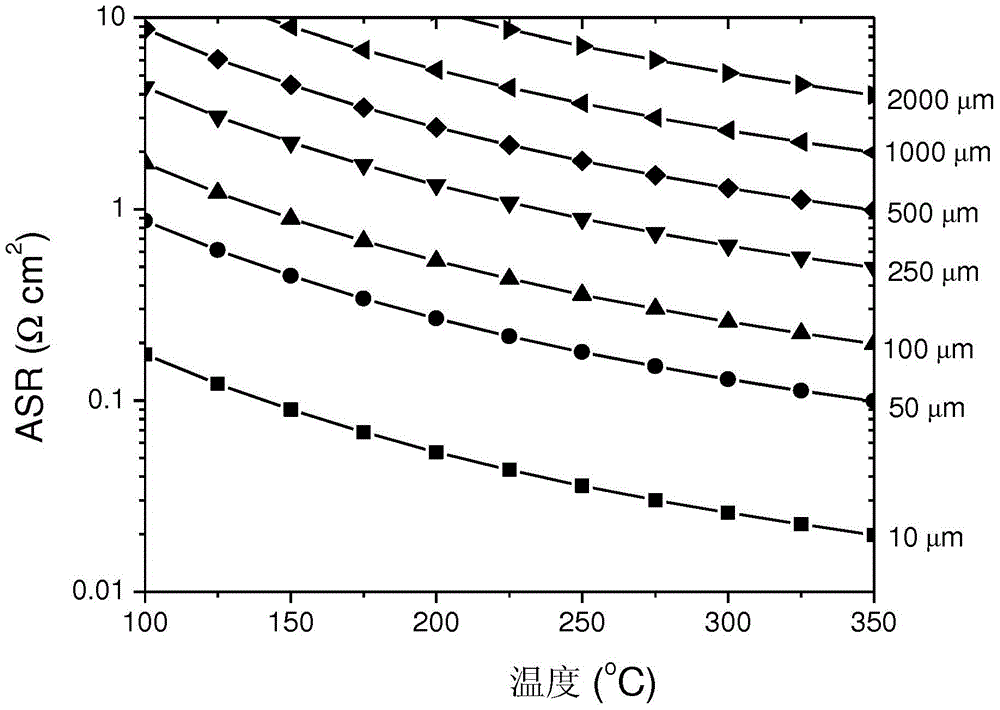
[0056] Figure 6 The measurement of ionic conductivity using a four-point probe device is schematically described in . The four-point probe method measures the conductivity of solid-state ionic conductors in a manner similar to the measurement of sheet resistivity by the so-called Vanderbilt technique (see Rev. Sci. Instrum. 76 (2005) 033907). The resistance is obtained by measuring the voltage (V) between the two inner probes 51 while flowing an AC current (I) between the two outer probes 53 (mounted on a layer of salt 55 for contact aid) . This measurement works well when the thickness (d) of the sample 57 is relatively small. Resistivity (p), which is the inverse of conductivity (σ), was calculated from the measured voltage and current together with a geometric correction factor (f). In the case of a film disc sample, the following formula is used.
[0057] ρ = 1 σ = π ...
Embodiment 3
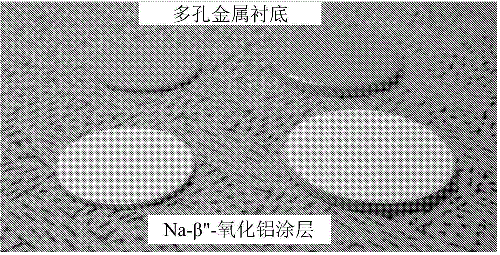
[0068] Coated disks prepared as described in Example 1 were subjected to repeated thermal cycling. Figure 7 shows the temperature profiles during a total of ten thermal cycles between 50°C (or room temperature) and 350°C. Photographs reveal coated Na-β"-Al after ten thermal cycles 2 o 3 The film layer was not broken and was not delaminated. This ensures that the thin-film sodium-conducting solid-state electrolyte is stable.
[0069] To maximize thermomechanical stability, the coefficient of thermal expansion (CTE) can be matched as close as possible between the substrate metal and the coated sodium conductive solid electrolyte film. Table 2 is the CTE and Na-β"-Al of several metals 2 o 3 Comparison chart of CTE. Metals with relatively high CTEs (eg, 316L SS) can still be used as substrates, since porous metals typically have a lower CTE than dense bodies. Therefore, all these commodity metals can be considered as coated substrates.
[0070] Table 2
[0071] Comparison...
PUM
| Property | Measurement | Unit |
|---|---|---|
| thickness | aaaaa | aaaaa |
| thickness | aaaaa | aaaaa |
| thickness | aaaaa | aaaaa |
Abstract
Description
Claims
Application Information
 - R&D
- Intellectual Property
- Life Sciences
- Materials
- Tech Scout
- Unparalleled Data Quality
- Higher Quality Content
- 60% Fewer Hallucinations
Browse by: Latest US Patents, China's latest patents, Technical Efficacy Thesaurus, Application Domain, Technology Topic, Popular Technical Reports.
© 2025 PatSnap. All rights reserved.Legal|Privacy policy|Modern Slavery Act Transparency Statement|Sitemap|About US| Contact US: help@patsnap.com


