Manufacturing method of faucet

A manufacturing method and faucet technology, which is applied in the field of faucet fittings, can solve problems such as harsh casting environment, easy to be scalded, and corroded, so as to improve production operability and external aesthetics, reduce product defect rate, and reduce production costs. Effect

Active Publication Date: 2015-06-10
JCL IND CO LTD
View PDF8 Cites 3 Cited by
  • Summary
  • Abstract
  • Description
  • Claims
  • Application Information

AI Technical Summary

Problems solved by technology

[0007] However, for the manufacture of faucet fittings body through casting operations, the environmental pollution is relatively large during the operation process, and the harmful components (graphite and impurities, etc.) on the characteristics of casting operations will remain in the body, when it is installed and used as a product When, especially in the drinking water part, there is a problem of harmfulness to the human body
At the same time, the environment associated with casting operations is harsh, so this method is generally not used now
[0008] In addition, for the actual use of the faucet fittings body as a product, the long-term use of the faucet fittings will cause the interior of the faucet fittings body to be corroded by tap water compared to the initial product, which will seriously affect hygiene.
[0009] In addition, when hot water is used, the body of the faucet fittings made of brass transfers heat faster. When the elderly or children touch the body, they may be easily burned if they are not careful.

Method used


Image

  • Manufacturing method of faucet
  • Manufacturing method of faucet
  • Manufacturing method of faucet

Examples


Embodiment 1

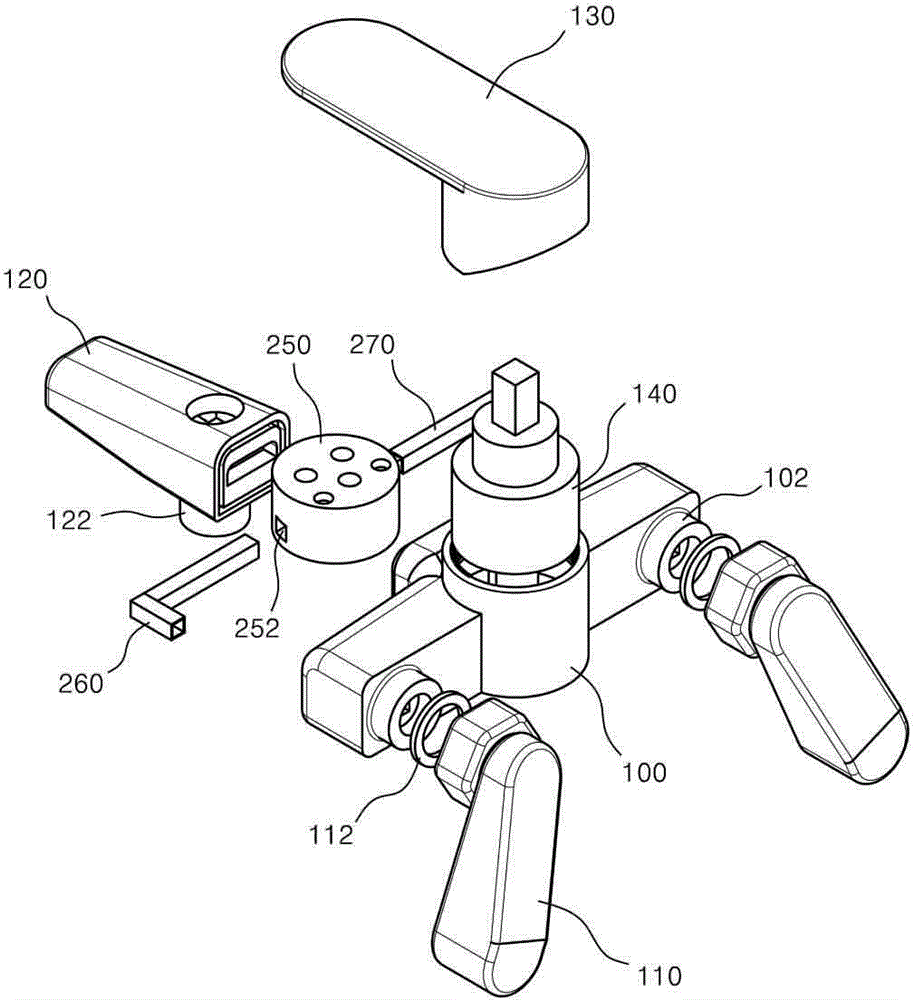
[0063] Figure 1 to Figure 2 It is an exploded perspective view of the faucet fittings manufactured by the faucet fittings manufacturing method according to an embodiment of the present invention, Figure 6 It is a process flow diagram of a method for manufacturing faucet fittings according to an embodiment of the present invention, Figure 1 to Figure 2 The same constituent elements are assigned the same reference numerals.

[0064] Referring to the above drawings, it can be seen that the faucet fittings manufacturing method according to one embodiment of the present invention includes: accessories preparation step S11, cold and hot water flow pipe joining step S12, double injection molding step S13 and assembly step S14.

[0065] First, prepare accessory S11 for manufacturing faucet fittings. The accessories here include metal accessories and non-metal accessories. The metal fittings include: an eccentric sleeve 110 connected to the cold and hot water pipes (not shown) on t...

Embodiment 2

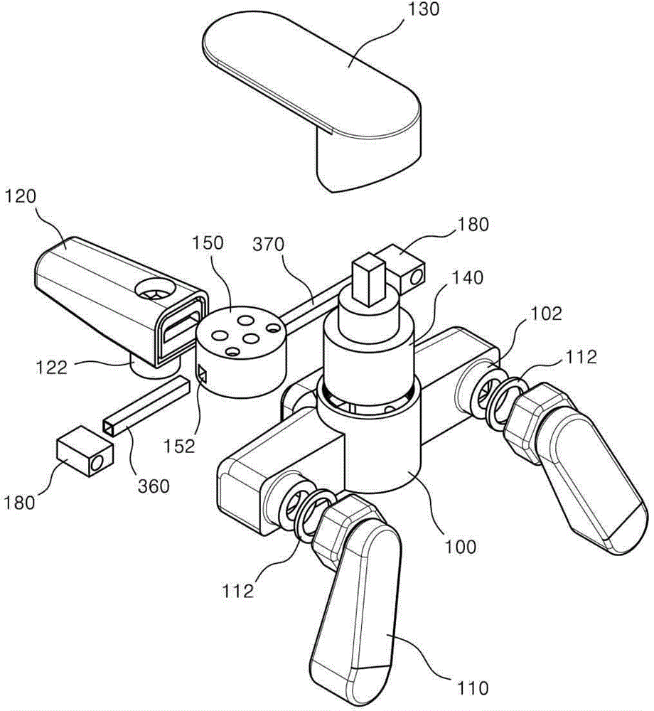
[0086] image 3 is an exploded perspective view of a faucet fitting manufactured by a faucet fitting manufacturing method according to another embodiment of the present invention, in image 3 neutralize Figure 1 to Figure 2 The same constituent elements are given the same reference numerals.

[0087] Referring to the above drawings, it can be seen that the manufacturing method of the faucet fittings according to another embodiment of the present invention is the same as the manufacturing method of the faucet fittings described in the foregoing embodiment 1, including: a step of preparing accessories; a step of combining cold and hot water flow pipes; a double injection molding step; and an assembly step.

[0088] Prepare metallic and non-metallic fittings in the fitting preparation step.

[0089] The metal accessories include: an eccentric sleeve 110 , a discharge pipe 120 , a water outlet 122 and an opening and closing handle 130 .

[0090] In addition, the non-metal fitt...

Embodiment 3

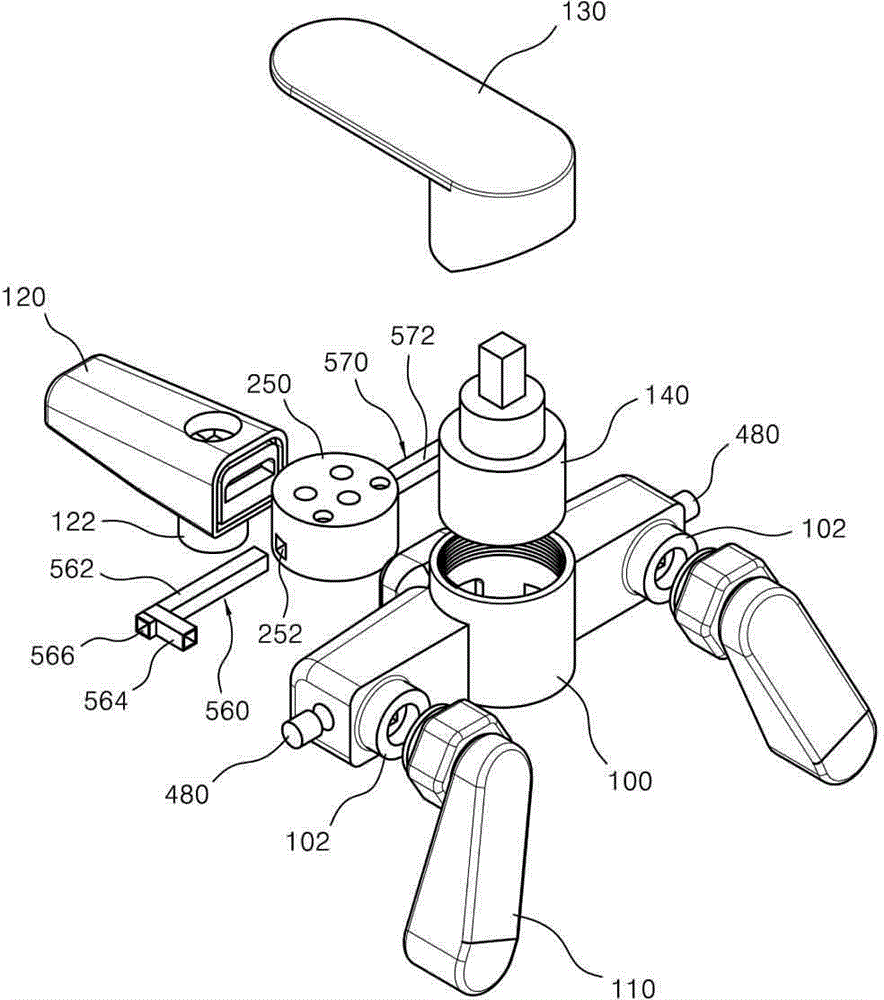
[0110] Figure 4 to Figure 5 is an exploded perspective view of a faucet fitting manufactured by a faucet fitting manufacturing method according to another embodiment of the present invention, in Figure 4 to Figure 5 neutralize Figure 1 to Figure 2 The same constituent elements are assigned the same reference numerals.

[0111] Referring to the above drawings, it can be seen that the manufacturing method of the faucet fittings according to another embodiment of the present invention is the same as the manufacturing method of the faucet fittings described in the foregoing embodiment 1, including: a step of preparing accessories; a step of combining cold and hot water flow pipes; a double injection molding step; and an assembly step.

[0112] Prepare metallic and non-metallic fittings in the fitting preparation step.

[0113] Metal fittings include: eccentric sleeve 110 , discharge pipe 120 , water outlet 122 , opening and closing handle 130 .

[0114] The non-metal fitting...


PUM


Abstract

A manufacturing method of a faucet according to an embodiment of the present invention comprises the steps of: (a) preparing metal parts for manufacturing a faucet, manifolds (150,250) for supplying provided cold water and hot water to an interruption member (140), and cold water and hot water flow pipes (260, 360, 270, 370); (b) connecting the cold water and hot water flow pipes (260, 270) to the manifold (250) or connecting the cold water and hot water flow pipes (360, 370) to a flow channel connecting member (180) and the manifold (150); (c) molding the manifolds (150, 250) to which the cold water and hot water flow pipes (260, 360, 270, 370) or the cold water and hot water flow pipes (260, 360, 270, 370) and the flow channel connecting member (180) are connected in a double injection mold, by injecting and filling an ABS resin of a liquid phase into a space part of the mold such that the manifolds (150, 250) to which the cold water and hot water flow pipes (260, 360, 270, 370) are connected and surrounded by a body (100); and (d) assembling the body (100) which accommodates the manifolds (150, 250) to which the cold water and hot water flow pipes (260, 360, 270, 370) are connected with other parts to form a faucet.

Description

technical field [0001] The invention relates to a method for manufacturing faucet fittings. Specifically, it relates to a method of manufacturing a control valve (hereinafter referred to as "faucet fittings") that is installed on equipment such as a washbasin, a bathtub, a shower, and a sink snake-shaped faucet so that water can be used, and the products manufactured thereby. Faucet fittings. Background technique [0002] Generally, faucets are installed and used on washbasins, bathtubs, showers, and sink faucets in bathrooms, and are connected to boilers so that hot and cold water can be used. [0003] That is to say, the faucet fittings are not restricted by a specific place, after it is connected to the front end of the cold and hot water pipes in the buried state, the water supply and water cut-off of the water supply can be freely adjusted by operating the opening and closing handle, and at the same time, the cold and hot water can be adjusted freely. The amount of mi...

Claims


Application Information

Patent Timeline
Patent Type & Authority Applications(China)
IPC IPC(8): F16K11/14F16K11/074F16K27/04
CPCF16K11/074F16K11/14F16K27/045E03C1/042Y10T29/49432E03C1/0404
Inventor 李在春
Owner JCL IND CO LTD
Why Eureka
Try Eureka