Self-supporting wide gap heat exchanging element

A heat exchange element, wide-gap technology, applied in the field of self-supporting wide-gap heat exchange elements, can solve the problems of difficult to control positioning accuracy, difficult to grasp welding deformation, and difficult to circulate smoke and gas, so as to reduce maintenance costs, design economical, The effect of convenient online cleaning

Active Publication Date: 2015-06-10
SHANDONG WINTECH TECH CO LTD
View PDF9 Cites 13 Cited by
  • Summary
  • Abstract
  • Description
  • Claims
  • Application Information

AI Technical Summary

Problems solved by technology

[0004] 1. Because multiple grids need to be spot-welded on each plate, and the grids need to be bent, not only the labor intensity is very high, but also the positioning accuracy is difficult to control. It is necessary to use special tooling to ensure the accuracy, and the investment in equipment is large
[0005] 2. Because there are many welds formed on the plate, it is difficult to control the welding deformation. At the same time, there are many welds, resulting in large welding stress. Stress corrosion cracking is prone to occur in a specific environment, and there is a large quality risk
[0006] 3. The channel formed by the slat bending grid has a large resistance drop in the forward direction of the fluid, which is not easy for the circulation of the smoke gas, resulting in a large fan power and high energy consumption required by the system.

Method used


Image

  • Self-supporting wide gap heat exchanging element
  • Self-supporting wide gap heat exchanging element
  • Self-supporting wide gap heat exchanging element

Examples


Embodiment Construction

[0028] Embodiments of the present invention are further described below in conjunction with accompanying drawings:

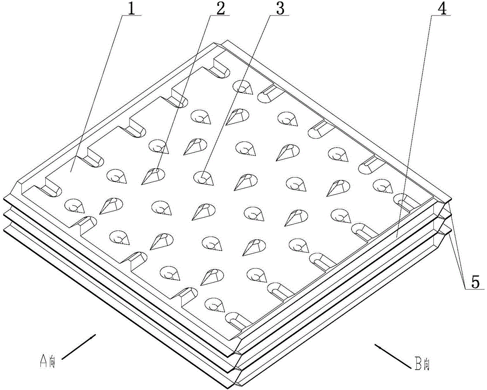
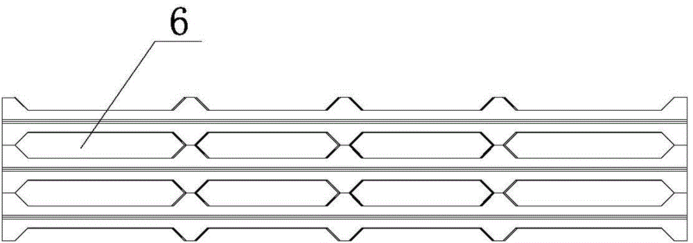
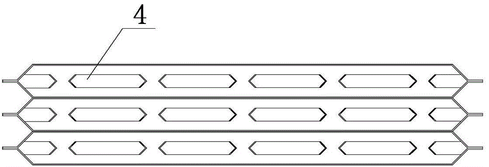
[0029] Such as Figure 1~3 As shown, the self-supporting wide-gap heat exchange element of the present invention includes several plate pairs 5 stacked in layers, and each plate pair 5 includes two upper and lower plates 1 oppositely arranged, and the upper surface of the plates 1 is along the Several rows of convex corrugations 2 and concave corrugations 3 are distributed in the direction of the same axis. Convex corrugations 2 and concave corrugations 3 are obtained by pressing plates upward and downward respectively. Convex corrugations 2 and concave corrugations are distributed at intervals. The concave corrugations and convex corrugations of the middle and upper plates correspond to the positions of the convex corrugations and concave corrugations of the lower plate respectively. One set of opposite sides of plate 1 is folded upwards and transitions to a pl...


PUM


Abstract

The invention is applicable to the field of air cold medium pre-heating and particularly relates to a self-supporting wide gap heat exchanging element. The self-supporting wide gap heat exchanging element comprises a plurality of plate pairs which are overlapped layer by layer; each plat pair comprises upper and lower plate sheets which are arranged oppositely; a plurality of rows of convex ripples and concave ripples are distributed on the upper surfaces of the plate sheets along the same axis direction; the convex ripples and concave ripples are obtained by upwards and downwards pressing and molding the plate sheets; the convex ripples and concave ripples are distributed at intervals; the positions of the convex ripples and concave ripples on the upper plate sheets in the plate pairs correspond to the positions of the convex ripples and concave ripples on the lower plate sheets in the plate pairs; one group of opposite edges of the plate sheets are upwards folded and are transited into planes; the other group of opposite edges of the plate sheets are downwards folded and are transited into planes; the two adjacent folding edges in each plate pair are welded to form an air channel; the two adjacent plate pairs are symmetrical up and down, and the adjacent folding edges between the two adjacent plate pairs are welded to form a flue gas channel. The self-supporting wide gap heat exchanging element has the advantages that a wide gap channel can be combined, dirt and dust are not easy to deposit, the resistance fall also can be reduced and the heat exchanging efficiency is sufficiently improved.

Description

technical field [0001] The invention relates to a self-supporting wide-gap heat exchange element, which is suitable for the field of air refrigerant preheating. Background technique [0002] The air refrigerant preheating device is a device for exchanging heat between the high-temperature flue gas produced by reforming furnaces, cracking furnaces, heating furnaces, steelmaking furnaces in the iron and steel industry, waste gas catalytic incinerators, hot blast stoves, etc., and the cold air used for combustion. The function is to cool the high-temperature flue gas, reduce harmful gas emissions, increase the temperature of the combustion air, and reduce energy consumption. [0003] In order to improve the fluency of flue gas and air, and avoid the problems of easy dust accumulation, scaling and corrosion in the channel, at present, the components of the existing air refrigerant preheating device usually adopt a wide gap combination structure, for example, Chinese Patent No. C...

Claims


Application Information

Patent Timeline
Patent Type & Authority Applications(China)
IPC IPC(8): F23L15/00F28F3/04F28F3/08
CPCY02E20/34
Inventor 杨立勇李振建关德军
Owner SHANDONG WINTECH TECH CO LTD
Why Eureka
Try Eureka