Direct current breaker bridge type module

A DC circuit breaker and bridge technology, which is applied to circuits, parts of protective switches, electrical components, etc., can solve the problem that the module unit structure can no longer be applied to DC circuit breakers, the power capacity of bridge modules cannot be improved, and parasitic parameters parasitic capacitance Control difficulties and other problems to achieve the effect of eliminating the hidden danger of explosion, reducing the total volume of the module, and improving the integration of the module

Active Publication Date: 2015-06-10
STATE GRID CORP OF CHINA +2
View PDF6 Cites 16 Cited by
  • Summary
  • Abstract
  • Description
  • Claims
  • Application Information

AI Technical Summary

Problems solved by technology

[0005] 1) The form of the fault is an open circuit, and it is prone to bursting when a fault occurs;
[0006] 2) The parasitic parameters of the device itself are relatively large, and the IGBTs in the module are connected through long busbars, which makes it extremely difficult to control the overall parasitic parameters (parasitic inductance, parasitic capacitance) of the bridge module, and it is easy to cause overcurrent and overvoltage phenomena;
[0007] 3) When soldered IGBTs are used in bridge modules, since the spacing of each IGBT is affected by surrounding components (laminated busbars, radiators, etc.), the power capacity per unit volume of the bridge module cannot be increased during layout.
[0008] The working principle and environment of DC circuit breakers make the existing modular unit structure no longer suitable for DC circuit breakers

Method used


Image

  • Direct current breaker bridge type module
  • Direct current breaker bridge type module
  • Direct current breaker bridge type module

Examples


Embodiment Construction

[0029] The specific implementation manners of the present invention will be further described in detail below in conjunction with the accompanying drawings.

[0030] In order to thoroughly understand the embodiments of the present invention, the detailed structure will be set forth in the following description. Obviously, the practice of the embodiments of the invention is not limited to specific details familiar to those skilled in the art. Preferred embodiments of the present invention are described in detail below, however, the present invention may have other embodiments besides these detailed descriptions.

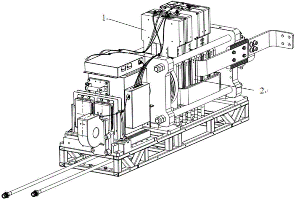
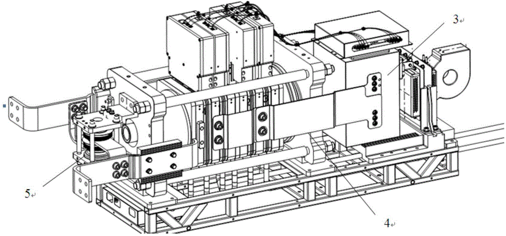
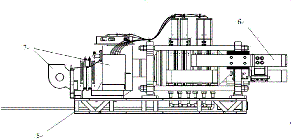
[0031] refer to Figure 1-Figure 3 , figure 1 It is a schematic diagram of the front structure of the DC circuit breaker bridge module in the figure of the present invention; figure 2 It is a schematic diagram of the back structure of the DC circuit breaker bridge module in the figure of the present invention; image 3 It is the front view of the DC circuit break...


PUM


Abstract

The invention discloses a direct current breaker bridge type module. The direct current breaker bridge type module comprises an IGBT (insulated gate bipolar translator) press fitting unit, a capacitor bank, a stack bus bar, a control unit, an energy supply unit and a support frame, wherein the capacitor bank is electrically connected with the IGBT press fitting unit through the stack bus bar, the capacitor bank is connected with the control unit and the energy supply unit, and the IGBT press fitting unit, the capacitor bank, the stack bus bar, the control unit and the energy supply unit are located on the support frame. By adopting the technical scheme, bursting hidden dangers of a traditional welded module under a failure state are eliminated, the integration level of the direct current breaker bridge type module is greatly improved, the overall size of the direct current breaker bridge type module is reduced, a voltage peak of the direct current breaker bridge type module is effectively reduced when a large current is cut off, and simultaneously a large heat radiating area is further provided to the control unit.

Description

technical field [0001] The invention relates to a DC circuit breaker for manufacturing a DC power grid, in particular to a DC circuit breaker bridge module. Background technique [0002] In power systems with large capacity and high voltage such as power plants and substations, the DC system provides reliable power for equipment such as relay protection, operation control, signal audio, and emergency lighting. As one of the most important components in the DC system, The stable and reliable operation of small DC circuit breakers will directly guarantee the safety of the entire power system; the vigorous development of the information industry has ushered in the great development of the communication power supply, EPS, UPS and other DC power supply industries, and base stations and data centers have sprung up in China On the earth, in order to ensure the high precision requirements of the DC power supply, the DC circuit breaker, which is the most important operation and prote...

Claims


Application Information

Patent Timeline
Patent Type & Authority Applications(China)
IPC IPC(8): H01H71/00
CPCH01H9/52H01H71/0207H01H2009/526H01H71/00
Inventor 王成昊张升汤广福贺之渊魏晓光高冲
Owner STATE GRID CORP OF CHINA
Why Eureka
Try Eureka