Quick well wall and wall back nondestructive detecting system based on transient electromagnetic method and detection method of the detection system

A transient electromagnetic method and non-destructive testing technology, applied in the direction of electric/magnetic detection for logging records, etc., can solve the problems of the influence of section interpretation work, unfavorable large-scale development, high construction conditions, etc., and achieve detection efficiency Improve and provide the effect of vertical resolution, small and light device

Inactive Publication Date: 2015-06-17
ANHUI HUIZHOU GEOLOGY SECURITY INST
View PDF8 Cites 8 Cited by
  • Summary
  • Abstract
  • Description
  • Claims
  • Application Information

AI Technical Summary

Problems solved by technology

[0003] Currently, ground-penetrating radar and ultrasonic methods are commonly used for wellbore quality inspection. Among them, the radar method is better for detecting internal defects of the wellbore wall and cavities behind the wall. In addition, the wellbore is closed, causing multiple reflections of electromagnetic waves in the wellbore, which also has a certain impact on the radar image (Reference: Pan Dongming et al. Ground penetrating radar in wellbore grouting

Method used


Image

  • Quick well wall and wall back nondestructive detecting system based on transient electromagnetic method and detection method of the detection system
  • Quick well wall and wall back nondestructive detecting system based on transient electromagnetic method and detection method of the detection system
  • Quick well wall and wall back nondestructive detecting system based on transient electromagnetic method and detection method of the detection system

Examples


Embodiment Construction

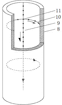
[0032] When there is a crack in the well wall or there is a cavity inside, and there is a cavity behind the wall due to incomplete grouting, especially when there is water conduction inside the diseased body, it will cause changes in the horizontal and vertical electrical characteristics of the well wall and the back of the wall. It provides a good basis for geophysical exploration for the transient electromagnetic method, which is sensitive to the difference in the electrical properties of the medium. The invention uses the transient electromagnetic method as a detection means to detect the defects on the well wall and behind the wall. The technical scheme is as follows:

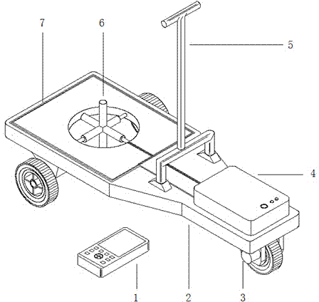
[0033] (1) Installation and connection of detection system; figure 1 As shown, the detection system is composed of two parts, the handheld 1 and the transient electromagnetic tackle 2. The handheld 1 communicates with the transmitter-receiver 4 through WIFI without cables. The transient electromagnetic tac...


PUM

PropertyMeasurementUnit
Lengthaaaaaaaaaa
Length and widthaaaaaaaaaa
Sizeaaaaaaaaaa

Abstract

The invention discloses a quick well wall and wall back nondestructive detecting system based on a transient electromagnetic method and a detection method of the detection system, in particular to a detecting system, and a detecting method and a construction process which are matched with the detecting system. The detecting system and the detecting method aim at detecting common defects such as well wall fractures, wall internal cavities, wall thickness issues and wall back holes in the shaft construction or use process, providing bases for subsequent improving schemes or remedial measures, and preventing hazards. Compared with the two common detecting technologies of a ground penetrating radar method and an ultrasonic method, the detecting system and the detecting method are remarkable in benefit and have the advantages that non-contact type measurement is achieved, and construction is easy, convenient and flexible; a three-component receiving probe is adopted, and the space resolving power of detection is ensured; fast scanning type detection can be achieved through a tackle gear and wireless communication; a non-metal structure and wall-attaching type arrangement are adopted, peripheral interference sources can be effectively distanced or avoided, and thus the signal to noise ratio can be increased; the dustproof and waterproof design is adopted for instrument equipment, and thus the continuous and stable work under harsh conditions can be ensured; the shaft construction condition is taken into consideration, and the safety factor is high.

Description

technical field [0001] The invention relates to the fields of shaft concrete well wall and back wall detection and geophysical nondestructive testing, in particular to a well wall and back wall rapid nondestructive testing system and a detection method based on a transient electromagnetic method. Background technique [0002] In order to improve the status quo of my country's shallow coal resources being gradually depleted, deep coal development is being carried out in many areas. In the development and construction of new deep coal wells, the wellbore often needs to pass through deep and thick water-bearing loose layers. At present, the freezing method is usually used for new well construction. As the throat of the whole mine, the quality and stability of the vertical shaft will directly affect the production and safety of the whole mine. As an important maintenance structure of the mine shaft, the shaft wall is currently mostly made of reinforced concrete or concrete stru...

Claims


Application Information

Patent Timeline
IPC IPC(8): G01V3/28
Inventor 唐润秋曹煜潘乐荀吴昭郝志超王宗涛任川褚洪河
Owner ANHUI HUIZHOU GEOLOGY SECURITY INST
Why Eureka
Try Eureka