
Confocal Laser Microscope Based on Self-mixing Interference and Its Scanning Method

A self-mixing interference, laser microscope technology, applied in the direction of using optical devices, measuring devices, instruments, etc., can solve the problems of complex system adjustment, small measurement field of view, increased measurement time, etc., to achieve strong beam divergence angle, easy adjustment of the optical path, The effect of good application prospects

Active Publication Date: 2017-10-20
NANJING UNIV OF INFORMATION SCI & TECH
View PDF3 Cites 0 Cited by
  • Summary
  • Abstract
  • Description
  • Claims
  • Application Information

AI Technical Summary

Problems solved by technology

However, this confocal system also has the disadvantage of being difficult to adjust the optical path sensitivity
At present, the confocal microscope is widely used in the fields of biomedicine and mechanical measurement, but the confocal microscope itself has certain shortcomings: first, it requires more optical components, and the performance requirements for the focusing lens and the photomultiplier tube used for signal detection Higher; the adjustment of the second system is complicated, especially the adjustment of the reflected light focusing on the pinhole requires special instruments and certain techniques; the third measurement field of view is small, and the measurement field of view of the general confocal laser microscope is within 10mm. If the measurement Large mechanical parts have to move the measurement platform multiple times to increase the measurement time

Method used


Image

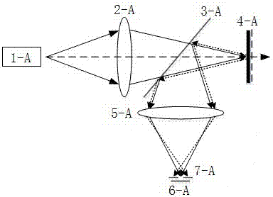
  • Confocal Laser Microscope Based on Self-mixing Interference and Its Scanning Method
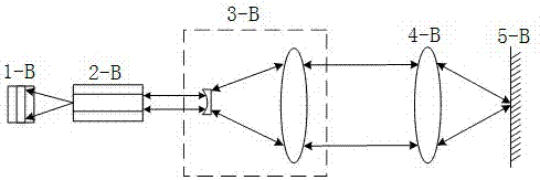
  • Confocal Laser Microscope Based on Self-mixing Interference and Its Scanning Method
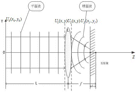
  • Confocal Laser Microscope Based on Self-mixing Interference and Its Scanning Method

Examples


Embodiment 1

[0033] Such as Figure 5 As shown, a confocal laser microscope based on self-mixing interference includes a helium-neon laser 1, a beam expanding collimating lens group 4-1 composed of a concave lens 4-1-1 and a convex lens 4-1-2, a variable center Sex density filter 5, objective lens 4-2, two-dimensional motion platform 7, one-dimensional motion platform 8, precision motion platform controller 9;

[0034] The He-Ne laser 1 is connected to the He-Ne laser power supply 2, and the forward emitting end axis of the He-Ne laser 1 is sequentially provided with a beam expander collimating lens group 4-1, a variable neutral density filter 5, and an objective lens 4 -2 and the target to be measured 6, the target to be measured 6 is fixed on the two-dimensional motion platform;

[0035] The helium-neon laser 1 outputs single longitudinal mode linearly polarized laser light in the forward direction, and the laser light passes through the beam expander and collimator lens group 4-1 and b...


PUM


Abstract

The invention discloses a confocal laser microscope based on self-mixing interference, which includes a helium-neon laser, a beam expander collimator lens group composed of a concave lens and a convex lens, a variable neutral density filter, an objective lens, a two-dimensional motion platform, One-dimensional motion platform, precision motion platform controller, photoelectric detector, current / voltage conversion circuit, filter, amplifier, analog / digital conversion circuit and computer unit; method of microscopic scanning using laser self-mixing interference and confocal principle Combining the advantages of simple structure and easy collimation of laser self-mixing technology and the characteristics of high axial resolution and strong anti-interference ability of confocal microscope, it solves the problem of autofocus and expanded measurement field of view of confocal laser microscope. It simplifies the structure of the traditional confocal microscope, reduces the difficulty of adjusting the reflection optical path in the confocal measurement system, and makes up for the characteristics of traditional confocal microscopes that require many optical components, high requirements for optical components, and difficult adjustment of the optical path.

Description

technical field [0001] The invention relates to the field of confocal laser microscopes, in particular to a self-mixing interference-based confocal laser microscope and a scanning method thereof. Background technique [0002] The research on self-mixing interference technology began in the 1960s, which means that the light incident on the outer surface is partially fed back and coupled into the inner laser cavity. The feedback injection of laser light mixes with the light in the laser cavity, which changes the output characteristics of the laser, such as causing changes in the spectrum and light intensity, forming a self-mixing effect. Since the 1980s, the principle of laser self-mixing interference has been applied to the field of measurement. In the late 1990s, domestic scholars began to pay attention to participating in the research of self-mixing theory and application. Compared with traditional interferometry technology, self-mixing interferometry has the same sensitiv...

Claims


Application Information

Patent Timeline
Patent Type & Authority Patents(China)
IPC IPC(8): G01B11/24
Inventor 宦海张雨黄凌霄卢松
Owner NANJING UNIV OF INFORMATION SCI & TECH
Learn More