Spiral Differential Inductor

A differential inductance and spiral technology, applied in the field of spiral differential inductors, can solve the problems of low Q value and large area of ​​differential inductors, and achieve the effect of increasing Q value, improving Q value, and good differential performance

Active Publication Date: 2018-09-25
SEMICON MFG INT (SHANGHAI) CORP
View PDF7 Cites 0 Cited by
  • Summary
  • Abstract
  • Description
  • Claims
  • Application Information

AI Technical Summary

Problems solved by technology

[0008] In view of the shortcomings of the prior art described above, the purpose of the present invention is to provide a spiral differential inductor to solve the problems of low Q value and large area of ​​the differential inductor in the prior art

Method used


Image

  • Spiral Differential Inductor
  • Spiral Differential Inductor
  • Spiral Differential Inductor

Examples


Embodiment 1

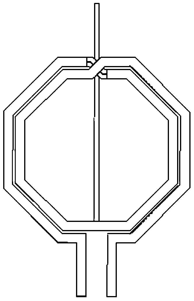
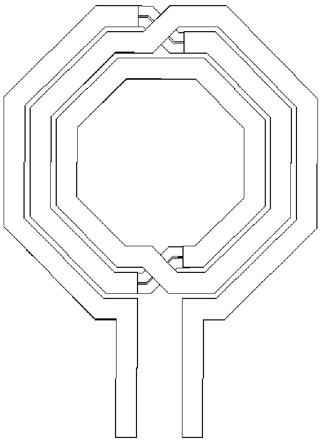
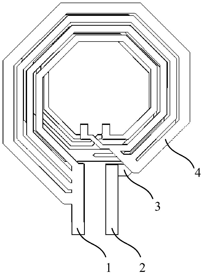
[0058] see Figure 3 to Figure 10 , the present invention provides a spiral differential inductor, comprising at least:

[0059] a first port and a second port opposite to the first port;

[0060] a bottom coil and a top coil formed over the bottom coil;

[0061] Both the bottom coil and the top coil are spiral coils; the outer end of the top coil is connected to the first port, the outer end of the bottom coil is connected to the second port, and the top coil and the The inner ends of the bottom coils are connected to each other to realize series connection;

[0062] The area of ​​the top coil is larger than the area of ​​the bottom coil.

[0063] See first image 3 , which is a structural schematic diagram of the spiral differential inductor of the present invention. As shown in the figure, the differential inductor includes a first port 1, a second port 2, a bottom coil 3 and a top coil 4, wherein the first port 1 is set opposite to the second port 2 , and the top laye...

Embodiment 2

[0074] This embodiment adopts basically the same technical solution as that of Embodiment 1. The difference is that in Embodiment 1, the line widths of all the metal lines in the branch line are the same, while in this embodiment, the spiral differential inductor is One half is brought out via a center tap for three-terminal differential performance.

[0075] Same as the first embodiment, this embodiment still takes the branch 42 in the outermost circle of the top layer coil 4 as an example for illustration. see Figure 11 , as shown in the figure, the outermost branch 42 of the top layer coil 4 is formed by parallel connection of four metal wires 421, wherein the wire width of the outer ring metal wire in the branch line is smaller than the line width of the inner ring metal wire. It should be pointed out that the line width of the outer ring metal wire is smaller than the line width of the inner ring metal wire may include the following situations: i) the line width of the ...

Embodiment 3

[0081] This embodiment adopts basically the same technical solution as that of Embodiment 2, except that, in Embodiment 2, a spiral differential inductor with two ends is used, while in this embodiment, it is a three-terminal differential inductor.

[0082] In the application of differential inductors, it is often necessary to connect a potential at the midpoint of the path of the metal coil, so the center tap line is drawn at this point to form a three-terminal differential inductor. The center tap is generally connected to the bias signal. see Figure 13 , which is a schematic structural diagram of a three-terminal spiral differential inductor in this embodiment. Except for the addition of the center tap 7, the structure of the spiral differential inductor in this embodiment is the same as that in Embodiment 2. For its specific structure, please refer to the relevant description in Embodiment 2, and details will not be repeated here.

[0083] see Figure 14 ,shown as Fig...


PUM


Abstract

The invention provides a spiral differential inductor. The spiral differential inductor comprises, at least, a first port, a second port opposite to the first port, a bottom layer coil and a top layer coil formed above the bottom layer coil. The bottom layer coil and the top layer coil are spiral coils. The outer end of the top layer coil is connected with the first port, the outer end of the bottom layer coil is connected with the second port, and the inner end of the top layer coil and the inner end of the bottom layer coil are mutually connected to achieve serial connection. The area of the top layer coil is greater than the area of the bottom layer coil. The first port and the second port of the spiral differential inductor can be well matched in Q performance and inductance performance, effective area of more than 30% can be saved, and the Q performance in a 1.8 GHz-5 GHz frequency band is greatly improved compared with a traditional inductor structure.

Description

technical field [0001] The invention belongs to the field of semiconductor devices and relates to a spiral differential inductor. Background technique [0002] At present, a large number of passive devices are included in integrated circuits, among which on-chip inductors are a very important one, and on-chip inductors are one of the important components of radio frequency CMOS / BiCMOS integrated circuits. In typical wireless products, inductive components have a significant impact on the overall RF performance. Therefore, the design and analysis of these inductive components have also been extensively studied. As the core component of the RF circuit, the inductor can usually affect the overall performance of the entire circuit. At present, on-chip inductors with high quality factors are widely used in RF circuit modules such as voltage-controlled oscillators and low-noise amplifiers. The Q value of the inductance quality factor is the main parameter to measure the inducta...

Claims


Application Information

Patent Timeline
Patent Type & Authority Patents(China)
IPC IPC(8): H01L23/522H01F17/00
Inventor 刘凌程仁豪王西宁
Owner SEMICON MFG INT (SHANGHAI) CORP
Why Eureka
Try Eureka