

Voltage-current double closed-loop terminal sliding mode control method of Buck converter
A technology of terminal sliding mode and control method, which is applied in the direction of DC power input conversion to DC power output, control/regulation system, instrument, etc., which can solve the problems of low response speed and steady-state precision, and achieve fast response speed and control accuracy High and low conservatism effects
- Summary
- Abstract
- Description
- Claims
- Application Information
AI Technical Summary
Problems solved by technology
Method used
Image

Examples
specific Embodiment approach 1
[0029] Specific embodiment one: 1, Buck converter voltage-current double closed-loop terminal sliding mode control method of the present embodiment, it is characterized in that it realizes according to the following steps:
[0030] Buck converter voltage-current double closed-loop terminal sliding mode control method, it is realized according to the following steps:
[0031] 1. Establishment of the mathematical model of the Buck converter;
[0032] 2. According to the output voltage V of the Buck converter C and the current i through the load L , to design the load observer;
[0033] 3. The design of the voltage terminal sliding mode controller: the voltage controller tracks the error e according to the given input DC voltage v Output inductor current given signal i L * ;
[0034] 4. The design of the current linear sliding mode controller: the current controller tracks the given signal i of the inductor current L * , output the control signal u of the controllable swi...
specific Embodiment approach 2
[0035] Specific implementation mode two: the difference between this implementation mode and specific implementation mode one is that step one is specifically:
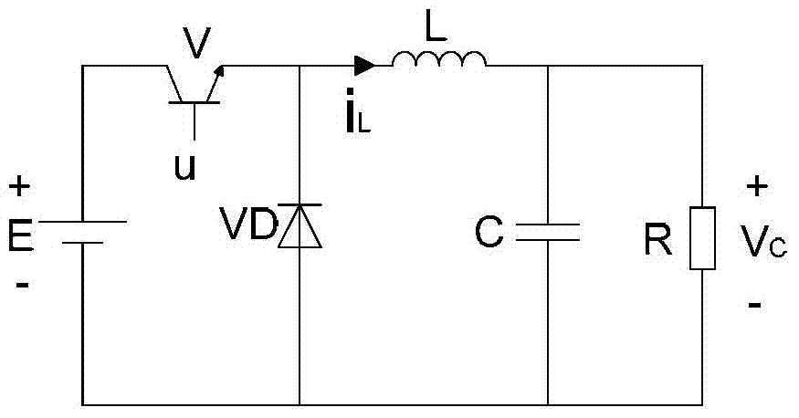
[0036] The circuit schematic diagram of the Buck converter is shown in figure 1 As shown, where E is the input DC voltage source, V is the controllable switch tube, and its working state is represented by u, V C is the output voltage, VD is the freewheeling diode, L is the filter inductance, C is the filter capacitor, R is the load resistance, Vc is the output voltage, i L is the inductor current.
[0037] Firstly, analyze the circuit characteristics of the Buck converter under the two conditions of "on" and "off" of the controllable switching tube V, and the corresponding working modes are represented by u=1 and u=0 respectively:
[0038] (1) When the controllable switch tube V is turned on, that is, u=1, the freewheeling diode VD is cut off under the reverse bias voltage, and the input DC power supply E is connect...
specific Embodiment approach 3
[0046] Specific implementation mode three: the difference between this implementation mode and specific implementation mode one or two is that the design of the load observer in step three is as follows:
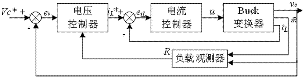
[0047] The proposed voltage-current double closed-loop Buck converter terminal sliding mode control scheme is as follows: figure 2 shown. The outer ring is the voltage ring, and the load observer is designed to overcome the disturbance effect of the unknown load resistance and track the error e according to the input DC voltage v Output inductor current given signal i L * , the inner loop is the current loop, and the current controller tracks the given signal i of the inductor current L * , and output the control signal u=1 or u=0 of the controllable switching tube V of the Buck converter. The design process of the current controller and the voltage controller is given in detail below.
[0048] The situation where the actual control system load R is unknown is conside...
PUM
| Property | Measurement | Unit |
|---|---|---|
| Inductance | aaaaa | aaaaa |
| Capacitance | aaaaa | aaaaa |
| Load resistance | aaaaa | aaaaa |
Abstract
Description
Claims
Application Information