Control method of medical filling pump and system using method

A control method and perfusion pump technology, applied in the field of medical devices, can solve problems such as inability to adapt to large flow perfusion, continuous perfusion, difficulty in ensuring surgical safety, and inability to confirm body cavity pressure, so as to shorten hospital stay, reduce treatment costs, The effect of simplifying manual steps

Active Publication Date: 2015-07-01
匡仁锐
View PDF13 Cites 14 Cited by
  • Summary
  • Abstract
  • Description
  • Claims
  • Application Information

AI Technical Summary

Problems solved by technology

[0007] The present invention provides a control method of a medical perfusion pump and a system using the method. The main technical problem to be solved is: the existing medical perfusion pump system usually only sets the upper limit of the output perfusion pressure and perfusion flow rate of the perfusion pump, However, the pressure in the body cavity cannot be confirmed, and the pressure in the body cavity is a key factor determining the safety of the operation, which makes it difficult to guarantee the safety of the operation; and in general scientific research experiments, a pressure sensor is installed at the end of the perfusion line inserted into the body cavity. Measure the real-time pressure, and then perform relevant calculations based on the measured data to realize the control of the working status of the external perfusion pump or suction pump. It is easy to be destroyed and dropped into the body cavity, and it is difficult to put into practical use; while another primitive method commonly used in the operation process is the use of manually controlled syringes, which can increase the safety of the operation, but cannot adapt to large flow perfusion, Continuous perfusion, and rely too much on the experience of the operator, resulting in high labor costs

Method used


Image

  • Control method of medical filling pump and system using method

Examples


Embodiment Construction

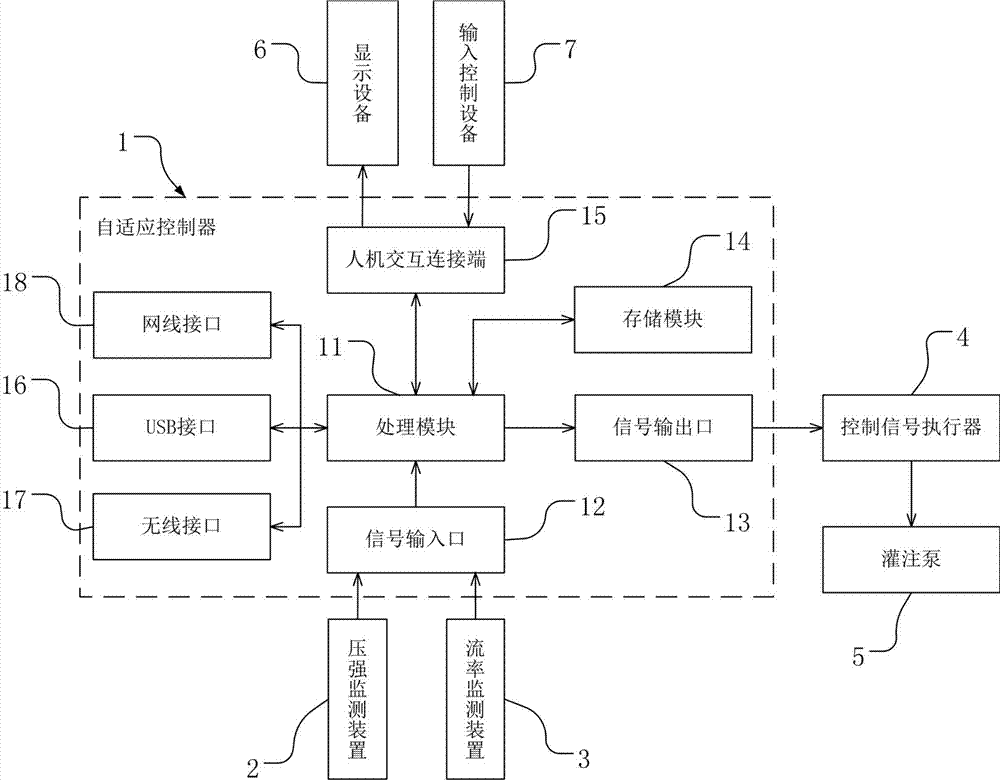
[0026] The following will be combined with figure 1 As well as the preferred embodiments, a method for controlling a medical perfusion pump proposed by the present invention and a system using the method are described in more detail.

[0027] The present invention provides a medical perfusion pump system, which includes an adaptive controller 1, a pressure monitoring device 2, a flow rate monitoring device 3, a control signal actuator 4 and a perfusion pump 5, the pressure monitoring device 2 (the pressure monitoring The device 2 may be a pressure sensor installed in the liquid medicine output pipe) on the perfusion pump 5, and the flow rate monitoring device 3 is used to monitor the output flow rate of the perfusion pump 5 (for example: using injection pump, the flow rate monitoring device 3 can be the displacement sensor of the stepping motor, by measuring the displacement of the stepping motor, the flow rate can be calculated according to the displacement per unit time and ...


PUM


Abstract

The invention provides a control method of a medical filling pump and a system using the control method. The system comprises an adaptive controller, a pressure monitoring device, a flow rate monitoring device, a control signal actuator and a filling pump; the pressure of a filling point can be accurately calculated according to output pressure of the filling pump, output flow rate of a filling pipeline of an endoscope, and static water pressure generated under the relative height between the output of a filling pipeline and the filling pump, so that the output flow rate of the filling pump can be accurately controlled according to the pressure of the filling point; the pressure monitoring device is not needed to be conveyed to a working point together with the endoscope, so that the manual operation can be effectively simplified, and the circumstance that the sensor is mechanically interfered to cause inaccurate measurement and is easily impacted by mistake by laser and damaged and even falls into the body can be avoided; in addition, the warning can be proposed according to the in-vivo pressure obtained by calculation and by setting and automatically adjusting the output flow rate, pressure and other indexes of the filling pump, thus the security can be ensured, and moreover, a small channel can be adopted, and as a result, a wide video field and high efficiency can be achieved.

Description

technical field [0001] The invention relates to the technical field of medical devices, in particular to an intelligent automatic control method for controlling a medical perfusion pump and a medical perfusion pump system using the method. Background technique [0002] Medical perfusion pumps are mainly used in various minimally invasive operations, and are necessary in many intracavitary operations in urology, and the performance of the perfusion pump and the operator's application method for the perfusion pump are crucial to the success of the operation. [0003] In the intracavitary operation of the kidney and ureter, inject normal saline into the body cavity to wash away bleeding and calculus powder during the operation, keep the vision of the ureteroscope, percutaneous nephroscope, and flexible ureteroscope clear, and can also open the cavity and maintain The space necessary for the operation, the heat generated by taking away the lithotripsy equipment, etc. This is ne...

Claims


Application Information

Patent Timeline
Patent Type & Authority Applications(China)
IPC IPC(8): A61B19/00A61M3/02A61M31/00
CPCA61M3/025A61M3/0254A61M31/00A61M2202/0007A61M2202/04
Inventor 匡仁锐
Owner 匡仁锐
Why Eureka
Try Eureka