Composite focus space-time synchronized drilling system and method

A drilling method and focus technology, applied in the field of compound focus space-time synchronous drilling system, can solve the problems of increasing processing procedures, reducing processing efficiency, and high product rejection rate

Active Publication Date: 2015-07-01
张立国
View PDF6 Cites 19 Cited by
  • Summary
  • Abstract
  • Description
  • Claims
  • Application Information

AI Technical Summary

Problems solved by technology

[0002] The current laser drilling is limited to a single laser focus drilling, and the dust generated by the drilling is still attached to the surroundings of the drilled microholes, the hole wall, etc. Improve the processing efficiency, and even make the product scrap rate remain high

Method used


Image

  • Composite focus space-time synchronized drilling system and method
  • Composite focus space-time synchronized drilling system and method
  • Composite focus space-time synchronized drilling system and method

Examples


Embodiment 1

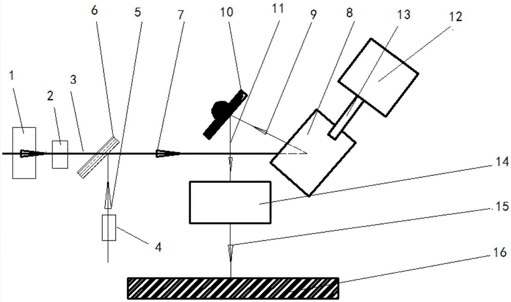
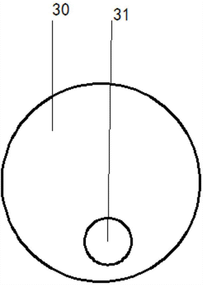
[0040] Embodiment 1. A multi-focus space-time synchronous drilling system suitable for blind holes of printed circuit boards. Combine below figure 1 with image 3 as well as Figure 4 The system provided in this embodiment will be described in detail.

[0041] figure 1 A schematic diagram of a system for drilling blind holes in printed circuit boards using the method provided in this embodiment, as shown in figure 1 As shown, the system provided in this embodiment includes a scanning motion drilling laser 1 , a scanning motion drilling laser modulator 2 , a heating and cleaning laser 4 , a laser beam combiner 6 , a laser focusing and focus switching module, and a workpiece 16 to be processed.

[0042] The scanning motion drilling laser 1 generates the first scanning motion drilling laser beam, and performs spatial motion modulation on it through the scanning motion drilling laser modulator 2, and the modulated first scanning motion drilling laser beam 3 incident laser comb...

Embodiment 2

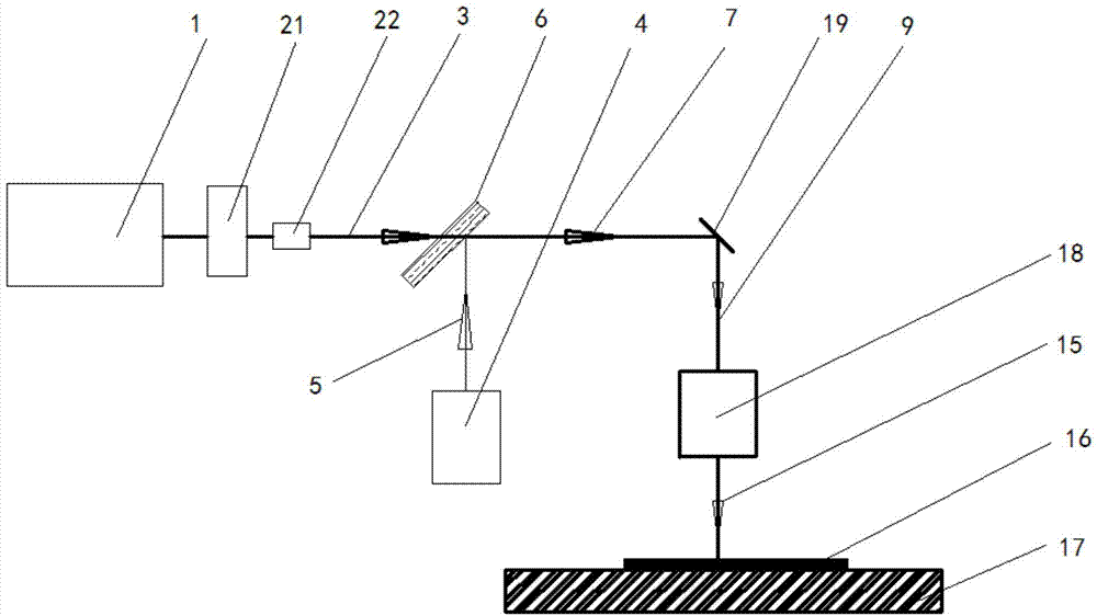
[0057] Embodiment 2. A composite focus space-time synchronous drilling system suitable for silicon wafer group holes. Combine below figure 2 , image 3 with Figure 4 The system provided in this embodiment will be described.

[0058] The composite focus space-time synchronous drilling system suitable for silicon wafer group holes has similarities with the composite space-time synchronous drilling system suitable for printed circuit boards in Embodiment 1, which can be found in figure 2 , The system provided in this embodiment includes a scanning motion drilling laser 1, a scanning motion drilling laser modulator 2, a heating and cleaning laser 4, a laser beam combiner 6, and a laser focusing and focus switching module.

[0059] Wherein, the scanning motion drilling laser modulator 2 is an acousto-optic deflector 21 and 22 placed orthogonally, it may also be an electro-optic deflector, it may also be a mirror driven by a piezoelectric ceramic or a galvanometer, or it may b...

Embodiment 3

[0068] Embodiment 3, a flow chart of a compound focus space-time synchronous drilling method. Combine below Figure 5 The method provided in this embodiment will be described in detail.

[0069] see Figure 5, the main working process of the method provided in this embodiment is: combining the first heating and cleaning laser beam and the first scanning motion drilling laser beam modulated by spatial motion to output the second heating and cleaning laser beam and the first Two scanning motion drilling laser beams form a laser beam group, so that the axis of symmetry of the spatial trajectory of the optical axis of the second scanning motion drilling laser beam is coaxial or paraxial with the optical axis of the second heating and cleaning laser beam, and the Paraxial means that the spatial angle between the axis of symmetry of the optical axis of the second scanning motion drilling laser beam and the optical axis of the second heating and cleaning laser beam is less than 10°...


PUM

PropertyMeasurementUnit
sizeaaaaaaaaaa
diameteraaaaaaaaaa
diameteraaaaaaaaaa

Abstract

The invention discloses a composite focus space-time synchronized drilling system and method. By means of the system, a drilling scanning space with the spot light size larger than the size of a drilling laser beam focus, or in other words, a laser heating and cleaning light beam focus (second laser focusing light spot) with time and space synchronized with those of the micro-hole drilling space forever, is arranged below a drilling optical focusing system, the heating and washing light beam conducts time-space synchronized laser preprocessing and laser washing on the scanning area of a scanning movement drilling laser beam focus (first laser focusing light spot), a large amount of laser processing time is saved, frequent phenomena of hole edge residual impurities, hole bottom residual resin and hole wall residual glass fiber of drilling devices especially printed circuit board blind hole devices are thoroughly eliminated, and the drilling finished product rate of micro-holes especially blind holes is greatly ensured. The quality problem of dense blind hole drilling is quite ingeniously solved.

Description

technical field [0001] The invention relates to the field of laser drilling processing, in particular to a composite focal point space-time synchronous drilling system and method. Background technique [0002] The current laser drilling is limited to a single laser focus drilling, and the dust generated by the drilling is still attached to the surroundings of the drilled microholes, the hole wall, etc. It reduces the processing efficiency and even makes the product scrap rate remain high. Because some micropores are too small, cleaning is a very big problem, and the present invention solves this problem exactly. Contents of the invention [0003] The technical problem to be solved by the present invention is to provide a compound focal point space-time synchronous drilling system and method. Multiple beams are focused by the same laser focusing system, wherein the scanning motion drilling laser beam in the multiple beams performs high-speed, high-precision and fine-spot f...

Claims


Application Information

Patent Timeline
Patent Type & Authority Applications(China)
IPC IPC(8): B23K26/382B23K26/046B23K26/70
Inventor 张立国
Owner 张立国
Why Eureka
Try Eureka