Vibration well cementation device and vibration well cementation method

A technology of cementing and oscillator, which is applied in the field of oil drilling and cementing, can solve the problems of limited range of vibration influence, influence on spud, high power, etc., and achieve the effect of simple AC wiring at the well site, low operating cost, and low energy loss

Inactive Publication Date: 2015-07-01
CHINA PETROCHEMICAL CORP +1
View PDF6 Cites 10 Cited by
  • Summary
  • Abstract
  • Description
  • Claims
  • Application Information

AI Technical Summary

Problems solved by technology

Since the installation position is at the wellhead, the downhole vibration effect is greatly attenuated by the transmission distance
(3) The hydraulic or air pulse vibration cementing device at the wellhead transmits the hydraulic or air pulse generated on the ground to the cement slurry in the annular space, but the ground pulse generating device and control system are huge and complex, and require a lot of power
The device finally stays at the bottom of the casing, which cannot be recycled, and the investment is high; the vibration influence range is limited after the bottom bumping floating hoop stops; the vibration time cannot be adjusted after entering the well, and it is difficult to judge the working state of the motor; the metal structure of the mechanical resonator is sealed The cavity will affect the continued drilling

Method used


Image

  • Vibration well cementation device and vibration well cementation method
  • Vibration well cementation device and vibration well cementation method
  • Vibration well cementation device and vibration well cementation method

Examples


Embodiment 1

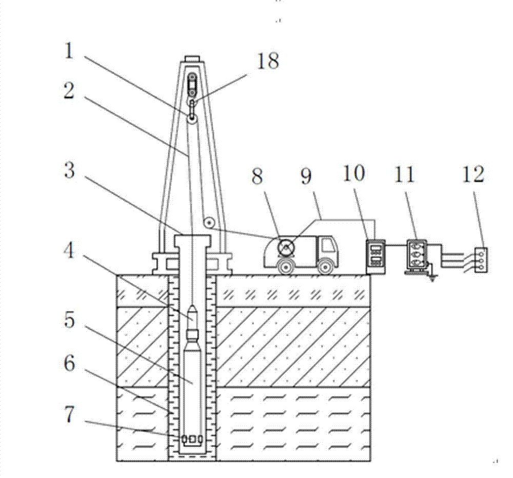
[0039] Refer to the attached figure 1 And attached figure 2 , in the vibration cementing device of the present invention, the ground uses a logging vehicle to load the cable 2, winch 8, frequency converter 10 and transformer 11, and the logging vehicle is equipped with a winch slip ring for transmitting alternating current. The cable 2 is a seven-core steel cable for well logging, and is wound on the well logging vehicle-mounted winch 8. One end of the cable is connected to the well logging horse head 4, and the other end is connected to the output end of the frequency converter 10 through the slip ring of the well logging winch. The input end of the frequency converter 10 is connected to the output end of the transformer 11, and the input end of the transformer 11 is connected to the 380V three-phase AC power supply at the well site.

[0040] The upper end of the oscillator 5 is connected with the tap 4, and the alternating current is transmitted through the pin of the tap....

Embodiment 2

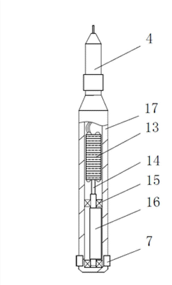
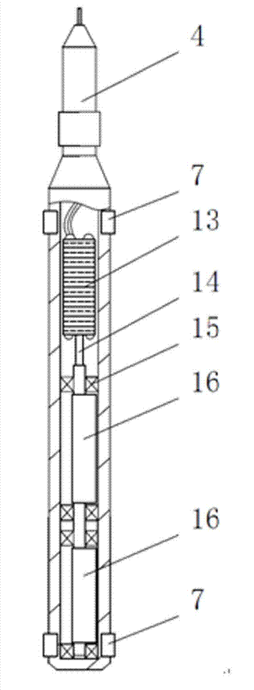
[0050] Refer to attached image 3 Compared with Embodiment 1, the eccentric block 16 of the vibratory cementing device is changed to two axially connected in series, and each is fixed in the pressure-resistant cavity 17 through a pair of bearings; the shell at the upper end of the oscillator 5 is also circumferentially embedded There are 3 to 8 rubber blocks 7, preferably 4, which can not only ensure that the low end of the oscillator 5 does not directly collide with metal, but also maintain a large enough flow channel between the rubber blocks, which is beneficial to Increase the lifting speed in the casing.

[0051] The length and quantity of the eccentric mass 16 can also be increased to increase the vibration force. The number of eccentric blocks 16 is changed from one to two in series, and the number of bearings is multiplied. Compared with a single eccentric load with the same total length, the load of a single bearing can be reduced and the life of the bearing can be i...

Embodiment 3

[0053] Compared with Embodiment 1, the cable 2 is directly fixedly connected to the oscillator 5 , the cable 2 is a steel cable with a load-bearing steel wire on the outside, and the steel wire is fixed on the top of the pressure chamber 17 by welding or riveting. The wires in the cable 2 are connected to the motor 13, and the motor 13 is fixed in the pressure chamber 17 with an interference fit. The large hook 18 on the derrick at the wellhead lifts the pulley 1 as the sky pulley, and cooperates with the ground pulley in the well logging engineering to better ensure the stability of the cable 2.

[0054] The other end of the cable 2 is directly connected to the output end of the transformer 11 through the winch slip ring. The total length of the cable 2 is 6 kilometers and the total resistance is 150Ω. The input end of the transformer 11 is connected to the power frequency 380V three-phase AC power supply at the well site, and the rated operating voltage of the motor is 380V....


PUM


Abstract

The invention discloses a vibration well cementation device and a vibration well cementation method. The vibration well cementation device mainly comprises a cable, a transformer and a vibrator. The vibration well cementation method includes demounting a cement head after well cementation slurry is replaced and pressing is finished, and extending the vibrator and the cable into a casing; starting the transformer and the vibrator to vibrate in an appointed well depth; letting the vibrator to go up or down as vibrating; stopping vibration of the vibrator and lifting the vibrator out of a well mouth when initial solidification time of cement slurry of a vibrating layer is up. Under the condition of having no influence on conventional well cementation process, annulus cement slurry is vibrated within the full range of the casing by a manner of transmitting vibration wave and beating the casing during cementation, flowing deformation characteristics of the cement slurry are improved, and well cementation quality is improved.

Description

technical field [0001] The invention relates to the technical field of petroleum drilling and cementing, in particular to a vibration cementing device and a vibration cementing method using the device. Background technique [0002] During the cementing process of oil and gas wells, affected by factors such as cement shrinkage, cement cracks and partial pores during the hydration process, and cement slurry column weight loss during the waiting period, the quality of the cementing is prone to unqualified wells, which will cause formation fluid to cross grooves in the later stage. affect oil and gas production. During the different stages of casing running, cement injection, cement replacement and cement slurry waiting, mechanical vibration, hydraulic pulse, hydraulic shock and other means can be used to generate vibration waves to act on the casing, drilling fluid and cement slurry to improve the cementing quality. [0003] The advantages and disadvantages of various vibratio...

Claims


Application Information

Patent Timeline
Patent Type & Authority Applications(China)
IPC IPC(8): E21B33/13
CPCE21B33/13
Inventor 安庆宝尹文波曲刚王新峰李亚伟高煜曾飞舟
Owner CHINA PETROCHEMICAL CORP
Why Eureka
Try Eureka