Engine indicating torque estimating method and engine indicating torque circulating circuit

A technology for indicating torque, engine, applied in the direction of engine components, machines/engines, mechanical equipment, etc., can solve problems such as transient errors, difficult cylinder sensor installation control or diagnostic tasks, complex models, etc.

Active Publication Date: 2015-07-01
LIANCHUANG AUTOMOBILE ELECTRONICS
View PDF4 Cites 5 Cited by
  • Summary
  • Abstract
  • Description
  • Claims
  • Application Information

AI Technical Summary

Problems solved by technology

However, both algorithms have their limitations: using the cylinder pressure estimation method, it is difficult to directly install the cylinder sensor on the engine to perform control or diagnostic tasks due to the high cost and poor durability of the cylinder pressure sensor, and the limitation of the engine installation space ; Using the crankshaft speed fluctuation estimation method, the crankshaft position is used to estimate the cylinder pressure and the indicated torque. The crankshaft position sensor used is cheap, easy to install, and has good stability. Complex, considering the computing power of the engine control unit (ECU), it is not suitable for online real-time estimation, and it will bring transient errors

Method used


Image

  • Engine indicating torque estimating method and engine indicating torque circulating circuit
  • Engine indicating torque estimating method and engine indicating torque circulating circuit
  • Engine indicating torque estimating method and engine indicating torque circulating circuit

Examples


Embodiment 1

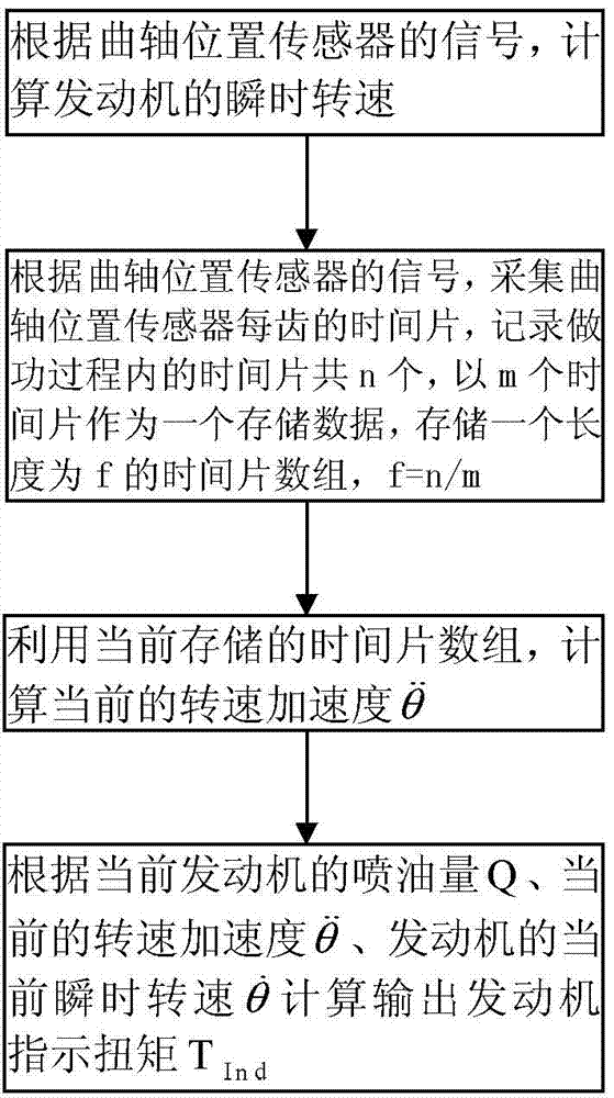
[0042] Engine indicated torque estimation methods such as figure 1 shown, including the following steps:

[0043] 1. Calculate the instantaneous speed of the engine according to the signal of the crankshaft position sensor;

[0044] Whether it is a two-stroke engine or a four-stroke engine, it must go through four working processes of air intake (scavenging), compression, combustion expansion (doing work), and exhaust to complete a working cycle. The difference is that in a four-stroke engine, every two revolutions of the crankshaft (720 degrees), the piston reciprocates twice, and the engine completes a working cycle, that is, every four strokes complete a working cycle. In a two-stroke engine, every time the crankshaft rotates once (360 degrees), the piston reciprocates once, and the engine completes a working cycle, that is, every two strokes complete a working cycle. Every time a two-stroke engine and a four-stroke engine complete a working cycle, the intake and exhaust ...

Embodiment 2

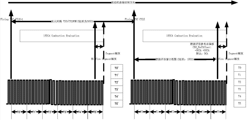
[0061] The collection and recording of the time slice needs to select the work process of the engine, and the calculation of the indicated torque needs to be completed in the current work process and before the next work process comes. Based on the engine indicated torque estimation method of embodiment 1, in step 2, the crankshaft position sensor adopts a crankshaft position signal disc with 58 teeth plus 2 missing teeth to collect the crankshaft position signal of the four-stroke engine, and there are 30 time slices in the work process. Every time slice of 5 teeth is used as a storage data T, and a time slice array with a length of 6 is stored. The specific collection and recording time is as follows figure 2 shown. In step 3, use the currently stored time slice array to calculate the current speed acceleration The specific algorithm is as follows:

[0062] θ . . = ( ...

Embodiment 3

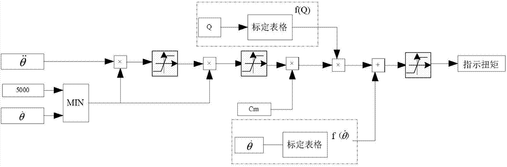
[0064] An indicated engine torque calculation circuit for realizing the engine indicated torque estimation method of Embodiment 1, such as image 3 As shown, it includes the speed acceleration calculation module, the small module, the load factor calculation module, the speed factor calculation module, the first multiplier, the second multiplier, the third multiplier, the fourth multiplier, the adder, the first upper and lower limits A limiting unit, a second upper and lower limit limiting unit, and a third upper and lower limit limiting unit;

[0065] The small module is used to output the smaller value of the two inputs;

[0066] The first upper and lower limit limiting unit, the second upper and lower limit limiting unit, and the third upper and lower limit limiting unit output a lower limit value when the input is less than the lower limit, output an upper limit value when the input is greater than the upper limit, and output an input value when the input is between the up...


PUM


Abstract

The invention discloses an engine indicating torque estimating method. The method comprises the steps of calculating the instantaneous rotation speed of an engine according to a signal of a crankshaft position sensor; collecting time slices of each tooth of the crankshaft position sensor, recoding the time slices during an acting process and storing a time slice array; utilizing the currently stored time slice array to calculate the current rotation speed acceleration; according to the current fuel-injection quantity Q of the engine, the current rotation speed acceleration and the current instantaneous rotation speed of the engine, calculating and outputting the engine indicating torque TInd. The invention discloses an engine indicating torque calculating circuit. According to the invention, the engine indicating torque can be calculated and output by utilizing the crankshaft position sensor and introducing the concept of rotation speed acceleration based on tooth time slices. Therefore, the indicating torque of the engine can be precisely estimated in real time.

Description

technical field [0001] The invention relates to engine technology, in particular to an engine indicated torque (combustion indication) estimation method and an engine indicated torque calculation circuit. Background technique [0002] Real-time estimation of engine indicated torque is of great significance for closed-loop control of traditional engine powertrain and online diagnosis of engine. At present, a variety of algorithms have been proposed for online estimation of engine indicated torque at home and abroad, mainly including cylinder pressure estimation method and crankshaft speed fluctuation estimation method. However, both algorithms have their limitations: using the cylinder pressure estimation method, due to the high cost and poor durability of the cylinder pressure sensor, and the limitation of the engine installation space, it is difficult to directly install the cylinder sensor on the engine to perform control or diagnostic tasks ; Using the crankshaft speed f...

Claims


Application Information

Patent Timeline
Patent Type & Authority Applications(China)
IPC IPC(8): F02B77/08
Inventor 崔丽吴瑾赵阳
Owner LIANCHUANG AUTOMOBILE ELECTRONICS
Why Eureka
Try Eureka