
Rotary control solid attitude and orbit control engine

A technology of orbit control engine and rotation control, which is applied in the direction of machines/engines, rocket engine devices, mechanical equipment, etc. It can solve the problems of poor control accuracy, high requirements of basic industry, ablation, etc., and achieve high reliability, simple structure, Facilitate the control effect

Inactive Publication Date: 2015-07-01
BEIHANG UNIV
View PDF6 Cites 25 Cited by
  • Summary
  • Abstract
  • Description
  • Claims
  • Application Information

AI Technical Summary

Problems solved by technology

[0004] Each small rocket engine in the above-mentioned pulse array attitude and orbit control system can only be ignited once, and continuous vector adjustment cannot be realized, so the control accuracy is poor; although the gas generator multi-nozzle attitude and orbit control system can realize continuous vector adjustment, However, due to the need to adjust the flow rate, the adjustment of the gas valve is used, which will lead to a series of problems such as thermal protection, ablation, and valve stem impact. It has high requirements for material technology and basic industries, and it is difficult to make technological breakthroughs. It has become a solid power technology development. technical bottleneck

Method used


Image

  • Rotary control solid attitude and orbit control engine
  • Rotary control solid attitude and orbit control engine
  • Rotary control solid attitude and orbit control engine

Examples


Embodiment Construction

[0038] The present invention will be further described in detail with reference to the accompanying drawings and embodiments.

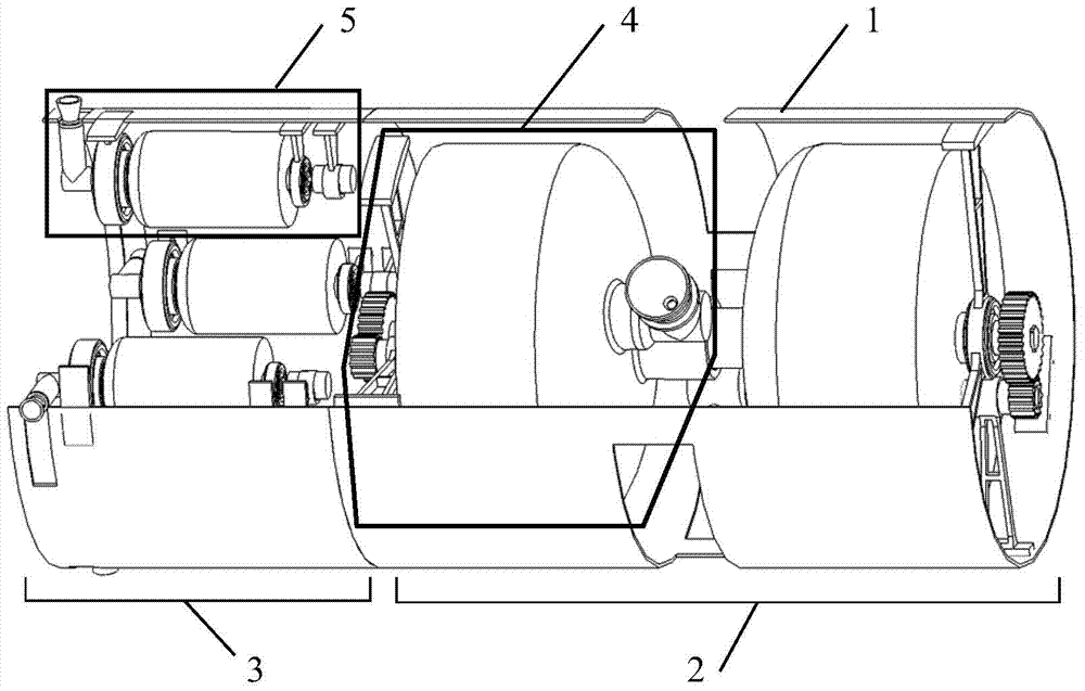
[0039] The present invention is a kind of rotation control solid state orbit control engine, such as figure 1 As shown, it includes an aircraft outer shell 1, an orbit control power system 2 and an attitude control power system 3.

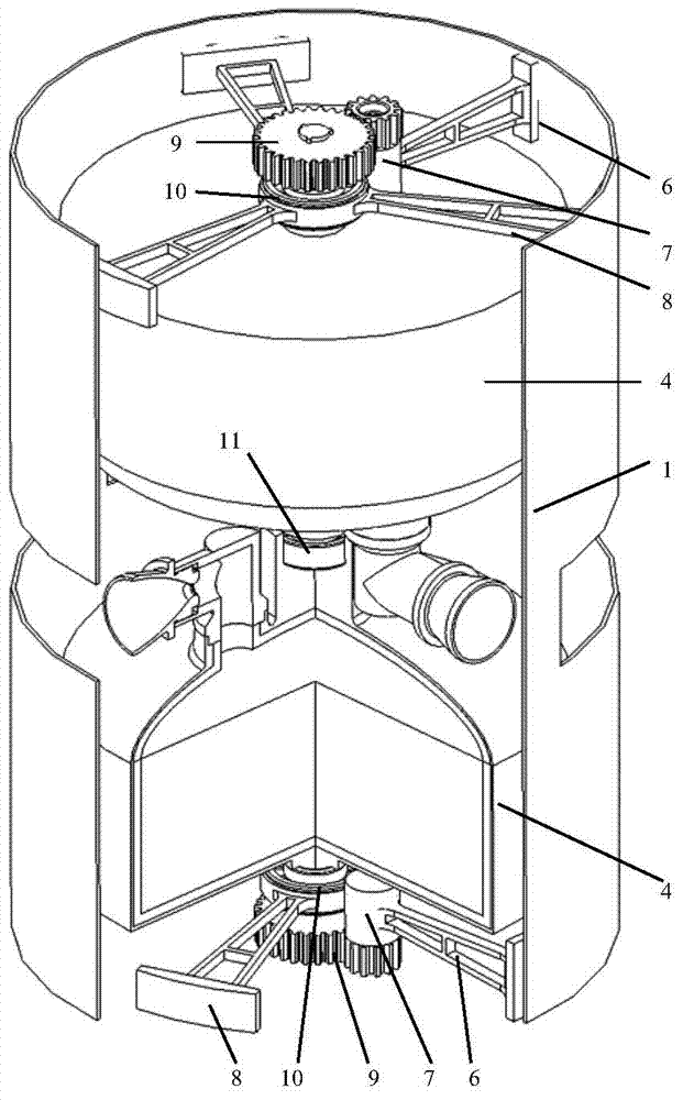
[0040] Such as figure 2 As shown, the orbital control power system 2 includes two orbital control engines 4;

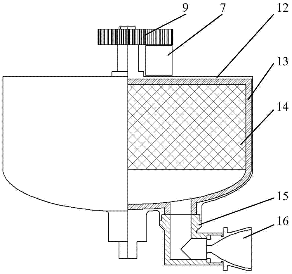
[0041] Orbital control engine 4 such as image 3 As shown, it includes a rail control engine casing 12, a rail control engine heat insulation layer 13, a rail control engine powder column 14, a rail control gas 90-degree pipeline 15, and a rail control engine nozzle 16;

[0042] Same as conventional solid rocket motors, between the orbital control engine housing 12 and the orbital control engine insulation layer 13, between the orbital control engine insulation layer 13 and the orbital control engine charge co...


PUM


Abstract

The invention discloses a rotary control solid attitude and orbit control engine which comprises an outer aircraft shell, an orbit control power system and an altitude control power system. Each orbit control engine comprises an orbit control engine shell, an orbit control engine insulating layer, an orbit control engine grain, an orbit control fuel gas 90-degree pipeline and an orbit control engine jet pipe, wherein the orbit control engine shell adheres to the orbit control engine insulating layer, the orbit control engine insulating layer adheres to the orbit control engine grain, one end of the orbit control fuel gas 90-degree pipeline is connected with an eccentric fuel gas channel of the orbit control engine shell, the other end of the orbit control fuel gas 90-degree pipeline is connected with the orbit control engine jet pipe, and the orbit control engine jet pipe is located on the mass center plane of the engine. The orbit control power system comprises two or more orbit control engines. The altitude control power system comprises three or more altitude control engines. Upper output shafts of the altitude control engines are connected with inner rings of upper altitude control rolling bearings, the outer rings of the upper altitude control rolling bearings are fixedly connected with upper altitude control engine supports, and orbit control engine supports are fixedly connected with the outer aircraft shell. The rotary control solid attitude and orbit control engine is low in technical difficulty, high in feasibility, simple in structure, high in reliability and flexible in form.

Description

technical field [0001] The invention relates to a rotation-controlled solid attitude and orbit control engine, which belongs to the technical field of rocket attitude and orbit control engines. Background technique [0002] The solid gas attitude and orbit control power system is mainly used in various types of missiles for air defense, anti-missile and space countermeasures. It relies on its own kinetic energy to kill and destroy threatening targets by collision. The overall weight is light and the volume is small. Motorized adjustment capability. [0003] In recent decades, major countries in the world have been carrying out research on new solid attitude and orbit control power systems used in the fields of air defense, anti-missile, anti-satellite and space countermeasures. The current solid propellant attitude and orbit control system can be divided into the following two types: one is the pulse array attitude and orbit control system, the missile is stabilized by spin...

Claims


Application Information

Patent Timeline
IPC IPC(8): F02K9/80
Inventor 任军学常桁刘宇王一白
Owner BEIHANG UNIV
Learn More