
Magneto-rheological damper

A magneto-rheological damper and damping cylinder technology, which is applied in the direction of shock absorbers, shock absorbers, springs/shock absorbers, etc., can solve the problems of large axial size, imperfection, and structural oscillation of the piston, and achieve increased The limit speed of the piston, good fail-safe ability, and the effect of preventing settlement and hardening

Active Publication Date: 2015-07-01
ACADEMY OF ARMORED FORCES ENG PLA
View PDF11 Cites 17 Cited by
  • Summary
  • Abstract
  • Description
  • Claims
  • Application Information

AI Technical Summary

Problems solved by technology

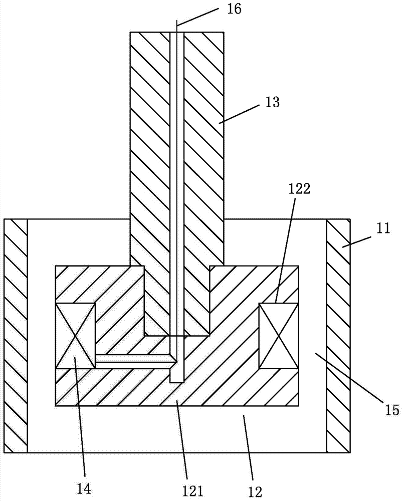
[0016] It can be seen that based on the structural design of the figure 1 When the adjustable multiple and adjustable damping force of the typical magnetorheological damper shown are adjusted, the adjustable multiple and adjustable damping force are contradictory, and unified adjustment cannot be implemented
[0017] Second, the residence time of magnetorheological fluid in the sensing channel is too short, and the piston limit speed and controllable damping force with controllable damping force are difficult to meet the requirements of high impact load at the same time
[0026] Third, the fail-safe mechanism is missing or imperfect
For example, if the magnetorheological damper in the vibration isolation device of construction machinery cannot provide enough damping force to consume the vibration energy after the electronic control system fails, the structure will vibrate when the equipment is working, thereby reducing the working accuracy and operation of the equipment. speed
[0028] Fourth, the anti-subsidence measures are missing or incomplete
The bottom valve of the existing double-tube magneto-rheological damper is very easy to block, while the bottom of the cylinder of the single-tube magnetorheological damper does not form backflow due to the liquid, and the settled ferromagnetic particles are not easy to redisperse, and may even be blocked by the piston. Constantly ramming
For the impact vibration system, if the magnetorheological fluid settles and hardens to block the valve hole or damping channel, the magnetorheological damper will be approximately a rigid device, and the sudden impact load will bring damage to the entire system , even with catastrophic consequences
[0030] Fifth, the axial size of the piston is large, which limits the effective stroke of the piston
However, for specific equipment, the axial installation space of the magneto-rheological damper is often limited, and the extended piston means that the effective stroke of the damper must be sacrificed, which again leads to a contradiction between the adjustable damping force and the effective stroke.

Method used


Image

  • Magneto-rheological damper
  • Magneto-rheological damper
  • Magneto-rheological damper

Examples


Embodiment Construction

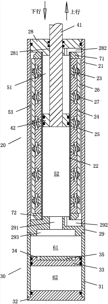
[0053] Such as figure 2 As shown, the magnetorheological damper of the present invention includes a damping cylinder 20, and a compensation cylinder 30 is connected to the bottom of the damping cylinder 20, wherein the damping cylinder 20 adopts a single rod double barrel structure, and the damping cylinder 20 includes a magnetically conductive outer cylinder 21 , The outer cylinder 21 is made of carbon steel or alloy steel pipe with good strength and magnetic conductivity, and a certain wall thickness is required to form the magnetic field line loop. The wall thickness must be determined by considering the magnetic flux and structural strength factors. A non-magnetic inner cylinder 22 is provided. The inner cylinder 22 is made of stainless steel or other non-magnetic pipe with better strength, and the wall thickness is required to be determined by considering the structural strength. The outer wall of the inner cylinder 22 is alternately sheathed A yoke ring 24 and a permanent...


PUM


Abstract

The invention discloses a magneto-rheological damper. The magneto-rheological damper comprises a damping cylinder and a compensating cylinder which are connected vertically. The damping cylinder comprises an outer cylinder, wherein an inner cylinder is arranged in the outer cylinder, the outer wall of the inner cylinder is alternatively sleeved with magnet yoke rings and a permanent magnet ring; a magnet exciting coil winds in an annular groove formed by adjacent magnet yoke rings and the permanent magnet ring between them; the magnet yoke rings and the magnet exciting coil are externally and alternatively sleeved with flux sleeve rings and magnet isolating sleeve rings; an annular damping channel is formed among the flux sleeve rings, the magnet isolating sleeve rings, and the inner wall of the outer cylinder; the upper and lower end openings of the outer cylinder are equipped with upper and lower end covers, and the inner cylinder is provided with a damping piston for dividing a damping cavity inside into upper and lower cavities; the upper and lower cavities are interconnected with the damping channel. The compensating cylinder comprises a cylinder body, wherein the upper end opening of the cylinder body is connected with the lower end cover, and the lower end opening of the cylinder body is equipped with the end cover; a compensating cavity forms in the cylinder body, and the cylinder body is provided with a floating piston for dividing the compensating cavity into fluid and gas cavities; the fluid cavity is interconnected with the lower cavity. The magneto-rheological damper solves the contradiction of adjustable damping force and adjustable multiple of the existing magneto-rheological damper, and is especially applicable to half-active control of an impact vibrating system.

Description

Technical field [0001] The invention relates to a magnetorheological damper for semi-active control of structural vibration, and belongs to the field of magnetorheological damper design. Background technique [0002] Magnetorheological damper is a kind of damping energy dissipation device that uses smart material-magnetorheological fluid as the working medium and changes the viscosity of the magnetorheological fluid by loading a magnetic field to achieve adjustable damping force. Its outstanding features are mainly With good controllability, simple structure and low energy consumption, it is an ideal device for realizing semi-active control of structural vibration. It has been widely used in various fields. However, in different application fields, there are huge differences in the working conditions of magnetorheological dampers. For example, in civil engineering, medical and other application fields, the piston movement speed of magnetorheological damper is low, and the magnet...

Claims


Application Information

Patent Timeline
Patent Type & Authority Applications(China)
IPC IPC(8): F16F9/53
CPCF16F9/3242F16F9/535
Inventor 彭志召张进秋刘峻岩张咏清滕涛王兴野彭虎姚军魏立刚
Owner ACADEMY OF ARMORED FORCES ENG PLA
Learn More